CRUISE CONTROL SYSTEM Cruise Control Switch Circuit
DESCRIPTION
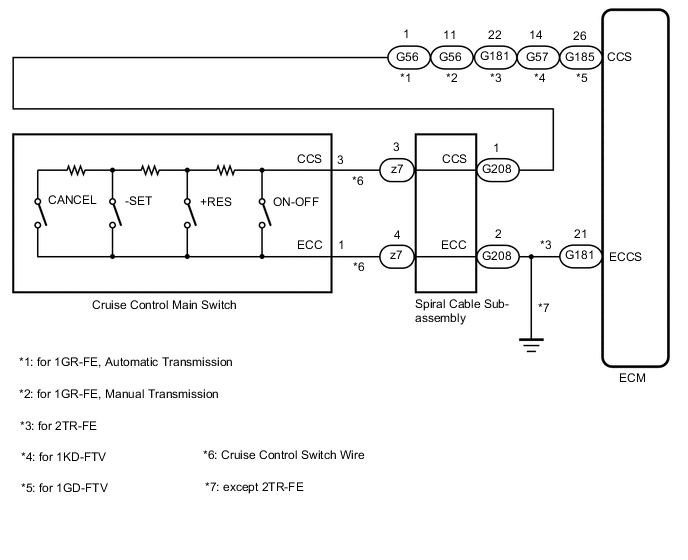
The cruise control main switch (ON-OFF button) is used to turn the cruise control system on and off, as well as operate 7 functions: SET, - (COAST), TAP-DOWN, RES (RESUME), + (ACCEL), TAP-UP and CANCEL. The SET, TAP-DOWN and - (COAST) functions, and the RES (RESUME), TAP-UP and + (ACCEL) functions are operated with the same switch. The cruise control main switch contains momentary type contacts for each function. The contacts close only while the cruise control main switch is being operated in the direction of the relative function arrow, and open when the cruise control main switch is released. The voltage at the terminal of the ECM changes as each of the different contacts open or close. The ECM reads this voltage and controls the SET, - (COAST), RES (RESUME), + (ACCEL), and CANCEL functions accordingly.
WIRING DIAGRAM
CAUTION / NOTICE / HINT
Note
-
The vehicle is equipped with a Supplemental Restraint System (SRS) which includes components such as airbags. Before servicing (including removal or installation of parts), be sure to read the precaution for Supplemental Restraint System.
-
Before replacing the ECM refer to Service Bulletin.
PROCEDURE
-
READ VALUE ON GTS
-
Connect the GTS to the DLC3.
-
Turn the ignition switch ON.
-
Turn the GTS on.
-
Enter the following menus: Powertrain / Cruise Control / Data List.
-
for 1GR-FE (for Manual Transmission):
Read the Data List according to the display on the GTS.
Powertrain > Cruise Control > Data List
Tester Display Measurement Item Range Normal Condition Diagnostic Note Main SW M-CPU Cruise control main switch signal (Main CPU) ON or OFF ON: Cruise control main switch on
OFF: Cruise control main switch off
- Cancel Switch CANCEL switch signal ON or OFF ON: CANCEL switch on
OFF: CANCEL switch off
- SET/COAST Switch -SET switch signal ON or OFF ON: -SET switch on
OFF: -SET switch off
- RES/ACC Switch +RES switch signal ON or OFF ON: +RES switch on
OFF: +RES switch off
- -
except 1GR-FE (for Manual Transmission):
Read the Data List according to the display on the GTS.
Powertrain > Cruise Control > Data List
Tester Display Measurement Item Range Normal Condition Diagnostic Note Cancel Switch CANCEL switch status ON or OFF ON: CANCEL switch on
OFF: CANCEL switch off
- -SET Switch -SET switch status ON or OFF ON: CANCEL switch on
OFF: CANCEL switch off
- +RES Switch +RES switch status ON or OFF ON: -SET switch on
OFF: -SET switch off
- Cruise Ready Main-CPU Cruise control system standby condition ON or OFF Each time cruise control main switch is pushed, ON or OFF changes - OK When the cruise control main switch is operated, the display changes as shown above. Result Proceed to OK NG
OK 
PROCEED TO NEXT SUSPECTED AREA SHOWN IN PROBLEM SYMPTOMS TABLE Click here
NG 
-
-
INSPECT CRUISE CONTROL MAIN SWITCH
-
Remove the cruise control main switch.
-
Inspect the cruise control main switch.
Result Proceed to OK NG
NG
REPLACE CRUISE CONTROL MAIN SWITCH Click here
OK
-
-
CHECK CRUISE CONTROL SWITCH WIRE
-
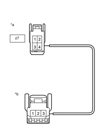
*a Front view of wire harness connector
(to Spiral Cable Sub-assembly)
*b Front view of wire harness connector
(to Cruise Control Switch)
Remove the cruise control switch wire.
-
Measure the resistance according to the value(s) in the table below.
Standard Resistance (Check for Open) Tester Connection Specified Condition Cruise control switch side connector terminal 3 - z7-3 Below 1 Ω Cruise control switch side connector terminal 1 - z7-4 Below 1 Ω Result Proceed to OK NG
NG
REPLACE CRUISE CONTROL SWITCH WIRE Click here
OK
-
-
INSPECT SPIRAL CABLE SUB-ASSEMBLY
-
Remove the spiral cable sub-assembly.
-
Inspect the spiral cable sub-assembly.
Result Proceed to OK NG
NG
REPLACE SPIRAL CABLE SUB-ASSEMBLY Click here
OK
-
-
CHECK HARNESS AND CONNECTOR (SPIRAL CABLE SUB-ASSEMBLY - ECM AND BODY GROUND)
-
Disconnect the G208 spiral cable sub-assembly connector.
-
Disconnect the G56*1, G57*2, G181*3 or G185*4 ECM connector.
-
*1: for 1GR-FE
-
*2: for 1KD-FTV
-
*3: for 2TR-FE
-
*4: for 1GD-FTV
-
-
Measure the resistance according to the value(s) in the table below.
Standard Resistance (for 1GR-FE, Automatic Transmission) Tester Connection Condition Specified Condition G208-1 (CCS) - G56-1 (CCS) Always Below 1 Ω G208-2 (ECC) - Body ground Always Below 1 Ω G208-1 (CCS) or G56-1 (CCS) - Body ground Always 10 kΩ or higher Standard Resistance (for 1GR-FE, Manual Transmission) Tester Connection Condition Specified Condition G208-1 (CCS) - G56-11 (CCS) Always Below 1 Ω G208-2 (ECC) - Body ground Always Below 1 Ω G208-1 (CCS) or G56-11 (CCS) - Body ground Always 10 kΩ or higher Standard Resistance (for 1KD-FTV) Tester Connection Condition Specified Condition G208-1 (CCS) - G57-14 (CCS) Always Below 1 Ω G208-2 (ECC) - Body ground Always Below 1 Ω G208-1 (CCS) or G57-14 (CCS) - Body ground Always 10 kΩ or higher Standard Resistance (for 2TR-FE) Tester Connection Condition Specified Condition G208-1 (CCS) - G181-22 (CCS) Always Below 1 Ω G208-2 (ECC) - G181-21 (ECCS) Always Below 1 Ω G208-1 (CCS) or G181-22 (CCS) - Body ground Always 10 kΩ or higher Standard Resistance (for 1GD-FTV) Tester Connection Condition Specified Condition G208-1 (CCS) - G185-26 (CCS) Always Below 1 Ω G208-2 (ECC) - Body ground Always Below 1 Ω G208-1 (CCS) or G185-26 (CCS) - Body ground Always 10 kΩ or higher Result Result Proceed to OK (except 2TR-FE) A OK (for 2TR-FE) B NG C
A
REPLACE ECM for 1GR-FE: Click here
REPLACE ECM for 1KD-FTV: Click here
REPLACE ECM for 1GD-FTV: Click hereC
REPAIR OR REPLACE HARNESS OR CONNECTOR
B
-
-
CHECK HARNESS AND CONNECTOR (ECM - BODY GROUND)
-
Disconnect the ECM connector.
-
Measure the resistance according to the value(s) in the table below.
Standard Resistance Tester Connection Condition Specified Condition C153-3 (E1) - Body ground Always Below 1 Ω Result Proceed to OK NG
OK
REPLACE ECM Click here
NG
REPAIR OR REPLACE HARNESS OR CONNECTOR
-