CRUISE CONTROL SYSTEM Clutch Switch Circuit
DESCRIPTION
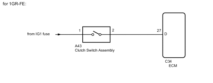
While depressing the clutch pedal, the clutch switch sends a signal to terminal D of the ECM. The ECM cancels cruise control when terminal D receives the signal.
WIRING DIAGRAM
CAUTION / NOTICE / HINT
Note
-
Inspect the fuses for circuits related to this system before performing the following inspection procedure.
-
Before replacing the ECM refer to Service Bulletin.
PROCEDURE
-
INSPECT CLUTCH SWITCH ASSEMBLY
-
Remove the clutch switch assembly.
-
Inspect the clutch switch assembly.
Result Proceed to OK NG
NG 
REPLACE CLUTCH SWITCH ASSEMBLY Click here
OK 
-
-
CHECK HARNESS AND CONNECTOR (CLUTCH SWITCH ASSEMBLY - BATTERY)
-
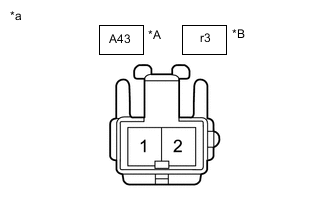
*A for LHD *B for RHD *a Front view of wire harness connector
(to Clutch Switch Assembly)
Disconnect the A43*1 or r3*2 clutch switch connector.
-
*1: for LHD
-
*2: for RHD
-
-
Measure the voltage according to the value(s) in the table below.
Standard Voltage (for LHD) Tester Connection Switch Condition Specified Condition A43-1 - Body ground Ignition Switch ON 11 to 14 V A43-1 - Body ground Ignition Switch off Below 1 V Standard Voltage (for RHD) Tester Connection Switch Condition Specified Condition r3-1 - Body ground Ignition Switch ON 11 to 14 V r3-1 - Body ground Ignition Switch off Below 1 V Result Proceed to OK NG
NG
REPAIR OR REPLACE HARNESS OR CONNECTOR
OK
-
-
CHECK HARNESS AND CONNECTOR (CLUTCH SWITCH ASSEMBLY - ECM)
-
for 1GR-FE
-
Disconnect the A43 clutch switch connector.
-
Disconnect the C34 ECM connector.
-
Measure the resistance according to the value(s) in the table below.
Standard Resistance Tester Connection Condition Specified Condition A43-2 - C34-27 (D) Always Below 1 Ω A43-2 or C34-27 (D) - Body ground Always 10 kΩ or higher
-
-
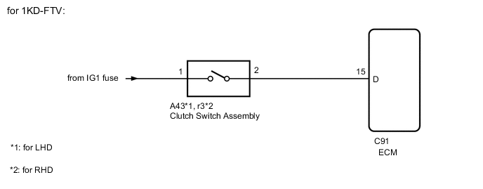
for 1KD-FTV
-
Disconnect the A43*1 or r3*2 clutch switch connector.
-
*1: for LHD
-
*2: for RHD
-
-
Disconnect the C91 ECM connector.
-
Measure the resistance according to the value(s) in the table below.
Standard Resistance (for LHD) Tester Connection Condition Specified Condition A43-2 - C91-15 (D) Always Below 1 Ω A43-2 or C91-15 (D) - Body ground Always 10 kΩ or higher Standard Resistance (for RHD) Tester Connection Condition Specified Condition r3-2 - C91-15 (D) Always Below 1 Ω r3-2 or C91-15 (D) - Body ground Always 10 kΩ or higher
-
-
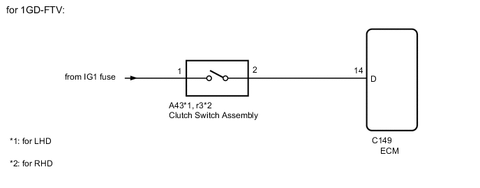
for 1GD-FTV
-
Disconnect the A43*1 or r3*2 clutch switch connector.
-
*1: for LHD
-
*2: for RHD
-
-
Disconnect the C149 ECM connector.
-
Measure the resistance according to the value(s) in the table below.
Standard Resistance (for LHD) Tester Connection Condition Specified Condition A43-2 - C149-14 (D) Always Below 1 Ω A43-2 or C149-14 (D) - Body ground Always 10 kΩ or higher Standard Resistance (for RHD) Tester Connection Condition Specified Condition r3-2 - C149-14 (D) Always Below 1 Ω r3-2 or C149-14 (D) - Body ground Always 10 kΩ or higher
Result Proceed to OK NG -
OK
REPLACE ECM for 1GR-FE: Click here
REPLACE ECM for 1KD-FTV: Click here
REPLACE ECM for 1GD-FTV: Click hereNG
REPAIR OR REPLACE HARNESS OR CONNECTOR
-