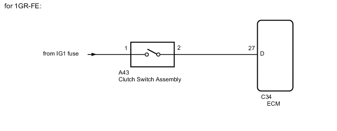
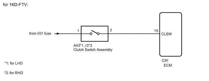
CRUISE CONTROL SYSTEM Clutch Switch Circuit
DESCRIPTION
While depressing the clutch pedal, the clutch switch sends a signal to terminal 27 (D)*1, 15 (CLSW)*2 or 14 (D)*2 of the ECM. The ECM cancels cruise control when terminal 27 (D)*1, 15 (CLSW)*2 or 14 (D)*3 receives the signal.
-
*1: for 1GR-FE
-
*2: for 1KD-FTV
-
*3: for 1GD-FTV
WIRING DIAGRAM

PROCEDURE
-
INSPECT CLUTCH SWITCH ASSEMBLY
-
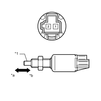
Text in Illustration *1 Pin *a Not pushed *b Pushed for LHD:
Remove the clutch switch Click here.
-
for RHD:
Remove the clutch switch Click here.
-
Measure the resistance according to the value(s) in the table below.
Standard Resistance Tester Connection Switch Condition Specified Condition 1 - 2 Pushed Below 1 Ω Not pushed 10 kΩ or higher Result Result Proceed to OK A NG (for LHD) B NG (for RHD) C
B 
REPLACE CLUTCH SWITCH ASSEMBLY Click here
C
REPLACE CLUTCH SWITCH ASSEMBLY Click here
A 
-
-
CHECK HARNESS AND CONNECTOR (CLUTCH SWITCH ASSEMBLY - BATTERY)
-
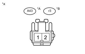
Text in Illustration *A for LHD *B for RHD *a Front view of wire harness connector
(to Clutch Switch Assembly)
Disconnect the A43*1 or r3*2 switch connector.
-
*1: for LHD
-
*2: for RHD
-
-
Measure the voltage according to the value(s) in the table below.
Standard Voltage for LHD Tester Connection Switch Condition Specified Condition A43-1 - Body ground Ignition switch ON 11 to 14 V Ignition switch off Below 1 V for RHD Tester Connection Switch Condition Specified Condition r3-1 - Body ground Ignition switch ON 11 to 14 V Ignition switch off Below 1 V
NG
REPAIR OR REPLACE HARNESS OR CONNECTOR
OK
-
-
CHECK HARNESS AND CONNECTOR (CLUTCH SWITCH - ECM)
-
*1: for LHD
-
*2: for RHD
-
*3: for 1GR-FE
-
*4: for 1KD-FTV
-
*5: for 1GD-FTV
-
Disconnect the A43*1 or r3*2 switch connector.
-
Disconnect the C34*3, C91*4 or C149*5 ECM connector.
-
Measure the resistance according to the value(s) in the table below.
Standard Resistance for 1GR-FE Tester Connection Condition Specified Condition A43-2 - C34-27 (D) Always Below 1 Ω A43-2 - Body ground Always 10 kΩ or higher for 1KD-FTV (for LHD) Tester Connection Condition Specified Condition A43-2 - C91-15 (CLSW) Always Below 1 Ω A43-2 - Body ground Always 10 kΩ or higher for 1KD-FTV (for RHD) Tester Connection Condition Specified Condition r3-2 - C91-15 (CLSW) Always Below 1 Ω r3-2 - Body ground Always 10 kΩ or higher for 1GD-FTV (for LHD) Tester Connection Condition Specified Condition A43-2 - C149-14 (D) Always Below 1 Ω A43-2 - Body ground Always 10 kΩ or higher for 1GD-FTV (for RHD) Tester Connection Condition Specified Condition r3-2 - C149-14 (D) Always Below 1 Ω r3-2 - Body ground Always 10 kΩ or higher
OK
PROCEED TO NEXT SUSPECTED AREA SHOWN IN PROBLEM SYMPTOMS TABLE Click here
NG
REPAIR OR REPLACE HARNESS OR CONNECTOR
-