CRUISE CONTROL SYSTEM, Diagnostic DTC:P0571
| DTC Code | DTC Name |
|---|---|
| P0571 | Brake Switch "A" Circuit |
DESCRIPTION
When the brake pedal is depressed, the stop light switch assembly sends a signal to the ECM. When the ECM receives this signal, it cancels control of vehicle speed by the cruise control system. The fail-safe function operates to enable normal driving even if there is a malfunction in the stop light switch assembly signal circuit. The cancellation condition occurs when voltage is applied to terminal STP. When the brake pedal is depressed, voltage is applied to terminal STP of the ECM through the STOP fuse and the stop light switch assembly, and the ECM cancels control of vehicle speed by the cruise control system.
| DTC No. | Detection Item | DTC Detection Condition | Trouble Area |
|---|---|---|---|
| P0571 | Brake Switch "A" Circuit | When the ignition switch ON and the cruise control system is operating, the voltage of the STP and ST1- terminals of the ECM are less than 1 V for 0.5 seconds or more. |
|
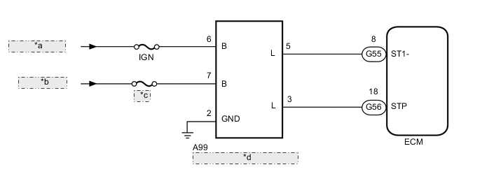
WIRING DIAGRAM

| *a | from IG2 Relay |
| *b | from Battery |
| *c | STOP |
| *d | Stop Light Switch Assembly |
| *a | from IG2 Relay |
| *b | from Battery |
| *c | STOP |
| *d | Stop Light Switch Assembly |
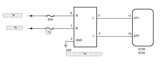
| *a | from IG2 Relay |
| *b | from Battery |
| *c | STOP |
| *d | Stop Light Switch Assembly |

| *a | from IG2 Relay |
| *b | from Battery |
| *c | STOP |
| *d | Stop Light Switch Assembly |

| *a | from IG2 Relay |
| *b | from Battery |
| *c | STOP |
| *d | Stop Light Switch Assembly |
CAUTION / NOTICE / HINT
Note
-
Inspect the fuses for circuits related to this system before performing the following procedure.
-
Before replacing the ECM, refer to Service Bulletin.
Tech Tips
After performing repairs on the vehicle, clear the DTCs and perform the following procedure to check that DTCs are not output.
-
Turn the ignition switch ON.
-
Turn the cruise control system on using the cruise control main switch (ON-OFF button).
-
Depress the brake pedal for 0.5 seconds or more.
PROCEDURE
-
CHECK HARNESS AND CONNECTOR (STOP LIGHT SWITCH ASSEMBLY - BATTERY AND BODY GROUND)
-
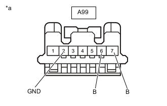
*a Front view of wire harness connector
(to Stop Light Switch Assembly)
Disconnect the A99 stop light switch assembly connector.
-
Measure the resistance according to the value(s) in the table below.
Standard Resistance Tester Connection Condition Specified Condition A99-2 (GND) - Body ground Always Below 1 Ω -
Measure the voltage according to the value(s) in the table below.
Standard Voltage Tester Connection Condition Specified Condition A99-7 (B) - Body ground Always 11 to 14 V A99-6 (B) - Body ground Ignition switch ON 11 to 14 V A99-6 (B) - Body ground Ignition switch off Below 1 V Result Proceed to OK NG
NG 
REPAIR OR REPLACE HARNESS OR CONNECTOR
OK 
-
-
INSPECT STOP LIGHT SWITCH ASSEMBLY
-
Inspect the stop light switch assembly.
Result Proceed to OK NG
NG
REPLACE STOP LIGHT SWITCH ASSEMBLY Click here
OK
-
-
CHECK HARNESS AND CONNECTOR (ECM - STOP LIGHT SWITCH ASSEMBLY)
-
for 1GR-FE, Automatic Transmission
-
Disconnect the A99 switch connector.
-
Disconnect the F56 ECM connectors.
-
Measure the resistance according to the value(s) in the table below.
Standard Resistance Tester Connection Condition Specified Condition F56-34 (ST1-) - A99-5 (L) Always Below 1 Ω F56-35 (STP) - A99-3 (L) Always Below 1 Ω F56-34 (ST1-) or A99-5 (L) - Body ground Always 10 kΩ or higher F56-35 (STP) or A99-3 (L) - Body ground Always 10 kΩ or higher
-
-
for 1GR-FE, Manual Transmission
-
Disconnect the A99 switch connector.
-
Disconnect the G55 and G56 ECM connectors.
-
Measure the resistance according to the value(s) in the table below.
Standard Resistance Tester Connection Condition Specified Condition G55-8 (ST1-) - A99-5 (L) Always Below 1 Ω G56-18 (STP) - A99-3 (L) Always Below 1 Ω G55-8 (ST1-) or A99-5 (L) - Body ground Always 10 kΩ or higher G56-18 (STP) or A99-3 (L) - Body ground Always 10 kΩ or higher
-
-
for 2TR-FE
-
Disconnect the A99 switch connector.
-
Disconnect the G180 ECM connectors.
-
Measure the resistance according to the value(s) in the table below.
Standard Resistance Tester Connection Condition Specified Condition G180-11 (ST1-) - A99-5 (L) Always Below 1 Ω G180-10 (STP) - A99-3 (L) Always Below 1 Ω G180-11 (ST1-) or A99-5 (L) - Body ground Always 10 kΩ or higher G180-10 (STP) or A99-3 (L) - Body ground Always 10 kΩ or higher
-
-
for 1KD-FTV
-
Disconnect the A99 switch connector.
-
Disconnect the G57 ECM connector.
-
Measure the resistance according to the value(s) in the table below.
Standard Resistance Tester Connection Condition Specified Condition G57-9 (ST1-) - A99-5 (L) Always Below 1 Ω G57-8 (STP) - A99-3 (L) Always Below 1 Ω G57-9 (ST1-) or A99-5 (L) - Body ground Always 10 kΩ or higher G57-8 (STP) or A99-3 (L) - Body ground Always 10 kΩ or higher
-
-
for 1GD-FTV
-
Disconnect the A99 switch connector.
-
Disconnect the G185 ECM connector.
-
Measure the resistance according to the value(s) in the table below.
Standard Resistance Tester Connection Condition Specified Condition G185-12 (ST1-) - A99-5 (L) Always Below 1 Ω G185-13 (STP) - A99-3 (L) Always Below 1 Ω G185-12 (ST1-) or A99-5 (L) - Body ground Always 10 kΩ or higher G185-13 (STP) or A99-3 (L) - Body ground Always 10 kΩ or higher
Result Proceed to OK NG -
OK
REPLACE ECM for 1GR-FE: Click here
REPLACE ECM for 1KD-FTV: Click here
REPLACE ECM for 1GD-FTV: Click here
REPLACE ECM for 2TR-FE: Click hereNG
REPAIR OR REPLACE HARNESS OR CONNECTOR
-