DYNAMIC RADAR CRUISE CONTROL SYSTEM, Diagnostic DTC:P0571
| DTC Code | DTC Name |
|---|---|
| P0571 | Brake Switch "A" Circuit |
DESCRIPTION
-
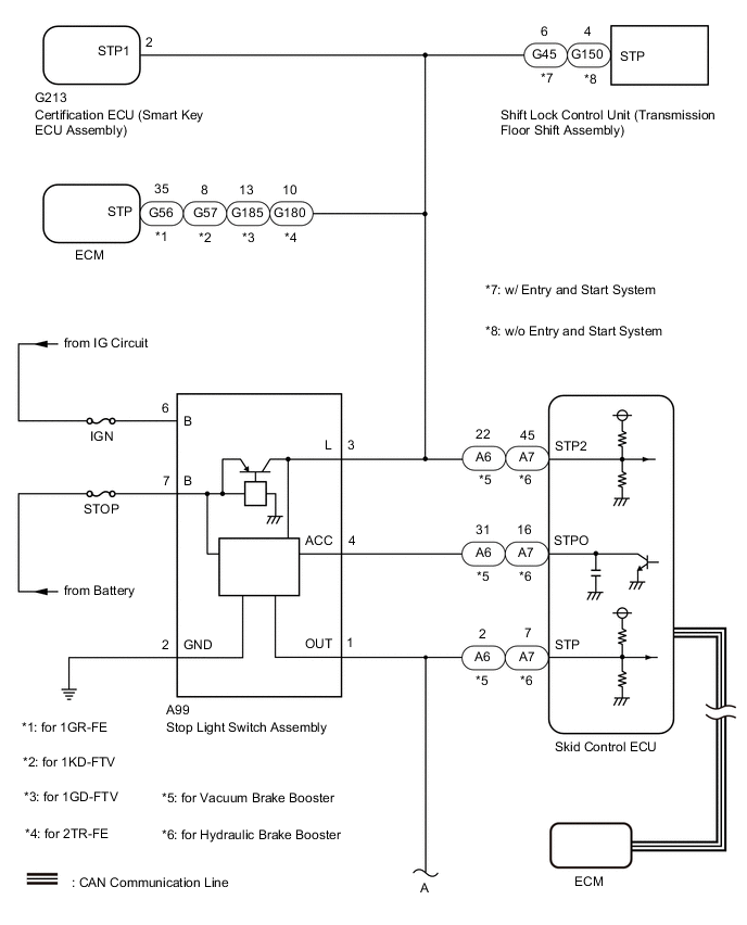
When the brake pedal is depressed, the stop light switch assembly sends a signal to the ECM. When the ECM receives this signal, it cancels the dynamic radar cruise control. The fail-safe function operates to enable normal driving even if there is a malfunction in the stop light signal circuit. The cancellation condition occurs when voltage is applied to terminal STP. When the brake is applied, voltage is normally applied to terminal STP of the ECM through the STOP fuse and the stop light switch assembly, and the ECM turns the dynamic radar cruise control system off.
Detection condition 1:
-
The ECM receives the brake demand signal from the driving support ECU assembly and transmits it to the skid control ECU. The skid control ECU receives a signal from the ECM and operates the skid control ECU. The skid control ECU operates the brake actuator assembly and at the same time illuminates the stop light by operating the stop light switch assembly.
Detection condition 2:
| DTC No. | Detection Item | DTC Detection Condition | Trouble Area |
|---|---|---|---|
| P0571 | Brake Switch "A" Circuit |
Condition 1:
Condition 2: |
Detection condition 1:
Detection condition 2: |
*1: for Vacuum Brake Booster
*2: for Hydraulic Brake Booster
WIRING DIAGRAM
CAUTION / NOTICE / HINT
Note
-
Before replacing the certification ECU (smart key ECU assembly), refer to smart entry and start system (for Entry Function) Precaution.
-
Before replacing the ECM, refer to Service Bulletin.
-
First perform the communication function inspections in How to Proceed with Troubleshooting to confirm that there are no CAN communication malfunctions before troubleshooting. Inspect the fuses for circuits related to this system before performing the following procedure.
-
Inspect the fuses for circuits related to this system before performing the following procedure.
-
When replacing the skid control ECU, perform zero point calibration.
for Vacuum Brake Booster: Click here
for Hydraulic Brake Booster: Click here
PROCEDURE
-
CHECK FOR DTCs (ENGINE CONTROL SYSTEM)
Tech Tips
Dynamic radar cruise control system DTC P0571 may be stored due to a malfunction in the engine control system. Therefore it is necessary to check for and troubleshoot engine control system DTCs first.
-
Connect the GTS to the DLC3.
-
Turn the ignition switch to ON.
-
Check for DTCs.
for 1GR-FE: Click here
for 1KD-FTV: Click here
for 1GD-FTV: Click here
for 1GD-FTV (w/ Urea SCR System): Click here
for 2TR-FE: Click here
Result Result Proceed to Engine control system DTCs are not output. A Engine control system DTCs are output. B
B 
GO TO ENGINE CONTROL SYSTEM for 1GR-FE: Click here
GO TO ENGINE CONTROL SYSTEM for 1KD-FTV: Click here
GO TO ENGINE CONTROL SYSTEM for 1GD-FTV: Click here
GO TO ENGINE CONTROL SYSTEM for 1GD-FTV (w/ Urea SCR System): Click here
GO TO ENGINE CONTROL SYSTEM for 2TR-FE: Click hereA 
-
-
CHECK TERMINAL VOLTAGE (STP, STPO AND STP2 TERMINAL)
-
for Vacuum brake booster
-
Turn the ignition switch off.
-
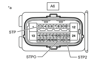
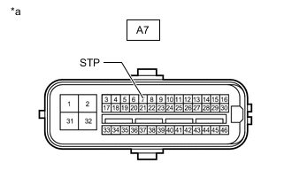
*a Front view of wire harness connector
(to Skid Control ECU (Brake Actuator Assembly))
Disconnect the skid control ECU (brake actuator assembly) connector.
-
Measure the voltage according to the value(s) in the table below.
Standard Voltage Tester Connection Condition Specified Condition A6-22 (STP2) - Body ground Brake pedal depressed 11 to 14 V Brake pedal released Below 1.5 V A6-31 (STPO) - Body ground Ignition switch ON 11 to 14 V A6-2 (STP) - Body ground Brake pedal depressed 11 to 14 V Brake pedal released Below 1.5 V
-
-
for Hydraulic brake booster
-
Turn the ignition switch off.
-
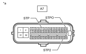
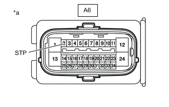
*a Front view of wire harness connector
(to Skid Control ECU (Master Cylinder Solenoid))
Disconnect the skid control ECU (master cylinder solenoid) connector.
-
Measure the voltage according to the value(s) in the table below.
Standard Voltage Tester Connection Condition Specified Condition A7-45 (STP2) - Body ground Brake pedal depressed 11 to 14 V Brake pedal released Below 1.5 V A7-16 (STPO) - Body ground Ignition switch ON 11 to 14 V A7-7 (STP) - Body ground Brake pedal depressed 11 to 14 V Brake pedal released Below 1.5 V
Result Result Proceed to All terminal voltage is normal A Only STP2 terminal voltage abnormal B Only STPO terminal voltage abnormal C Only STP terminal voltage abnormal D STPO terminal and STP terminal voltage abnormal E -
B 
INSPECT SKID CONTROL ECU Click here
C
CHECK HARNESS AND CONNECTOR (SKID CONTROL ECU - STOP LIGHT SWITCH ASSEMBLY) Click here
D
CHECK TERMINAL VOLTAGE (STP TERMINAL) Click here
E
CHECK HARNESS AND CONNECTOR (SKID CONTROL ECU - STOP LIGHT SWITCH ASSEMBLY) Click here
A
-
-
PERFORM ACTIVE TEST USING GTS (STOP LIGHT RELAY)
-
Enter the following menus: Chassis / ABS/VSC/TRC / Active Test.
-
Perform "Active Test" according to the display on the GTS.
Chassis > ABS/VSC/TRC > Active Test
Tester Display Measurement Item Control Range Diagnostic Note Stop Light Relay Stop light control relay (stop light switch assembly) Relay ON/OFF Stop lights come on
Vehicle condition: Vehicle stopped
OK Stop light turns ON/OFF in response to the GTS operation Result Proceed to OK NG
NG
INSPECT SKID CONTROL ECU Click here
OK
-
-
CHECK FOR DTC
-
Connect the GTS to the DLC3.
-
Turn the ignition switch to ON.
-
Clear the DTCs.
-
Enter the following menus: Chassis / ABS/VSC/TRC / Active Test.
-
Perform "Active Test" according to the display on the GTS.
Chassis > ABS/VSC/TRC > Active Test
Tester Display Measurement Item Control Range Diagnostic Note Stop Light Relay Stop light control relay (stop light switch assembly) Relay ON/OFF Stop lights come on
Vehicle condition: Vehicle stopped
-
Check for DTCs.
Result Result Proceed to DTC P0571 is output A DTC P0571 is not output B
A
REPLACE SKID CONTROL ECU for Vacuum Brake Booster: Click here
REPLACE SKID CONTROL ECU for Hydraulic Brake Booster (for LHD): Click here
REPLACE SKID CONTROL ECU for Hydraulic Brake Booster (for RHD): Click hereB
USE SIMULATION METHOD TO CHECK Click here
-
-
INSPECT SKID CONTROL ECU
-
Enter the following menus: Chassis / ABS/VSC/TRC / Active Test.
-
Perform "Active Test" according to the display on the GTS.
Chassis > ABS/VSC/TRC > Active Test
Tester Display Measurement Item Control Range Diagnostic Note Stop Light Relay Stop light control relay (stop light switch assembly) Relay ON/OFF Stop lights come on
Vehicle condition: Vehicle stopped
-
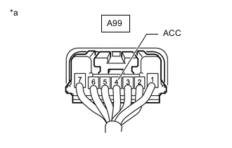
*a Component with harness connected
(Stop Light Switch Assembly)
Measure the voltage according to the value(s) in the table below.
Standard Voltage Tester Connection Condition Specified Condition A99-4 (ACC) - Body ground Active test is ON Below 1.5 V Result Proceed to OK NG
OK
REPLACE STOP LIGHT SWITCH ASSEMBLY Click here
NG
REPLACE SKID CONTROL ECU for Vacuum Brake Booster: Click here
REPLACE SKID CONTROL ECU for Hydraulic Brake Booster (for LHD): Click here
REPLACE SKID CONTROL ECU for Hydraulic Brake Booster (for RHD): Click here -
-
INSPECT SKID CONTROL ECU
-
for Vacuum brake booster
-
Turn the ignition switch off.
-
*a Front view of wire harness connector
(to Skid Control ECU (Brake Actuator Assembly))
Disconnect the skid control ECU (brake actuator assembly) connector.
-
Measure the voltage according to the value(s) in the table below.
Standard Voltage Tester Connection Condition Specified Condition A6-2 (STP) - Body ground Brake pedal released Below 1.5 V
-
-
for Hydraulic brake booster
-
Turn the ignition switch off.
-

*a Front view of wire harness connector
(to Skid Control ECU (Master Cylinder Solenoid))
Disconnect the skid control ECU (master cylinder solenoid) connector.
-
Measure the voltage according to the value(s) in the table below.
Standard Voltage Tester Connection Condition Specified Condition A7-7 (STP) - Body ground Brake pedal released Below 1.5 V
Result Proceed to OK NG -
NG
CHECK STOP LIGHT SWITCH ASSEMBLY Click here
OK
-
-
CHECK HARNESS AND CONNECTOR (SKID CONTROL ECU - ECM)
-
for Vacuum Brake Booster
-
Turn the ignition switch off.
-
Disconnect the A6 skid control ECU (brake actuator assembly) connector.
-
Disconnect the G180 ECM connector.
-
Measure the voltage according to the value(s) in the table below.
Standard Voltage Tester Connection Condition Specified Condition A6-22 (STP2) or G180-10 (STP) - Body ground Brake pedal depressed 11 to 14 V
-
-
for Hydraulic Brake Booster
-
Turn the ignition switch off.
-
Disconnect the A7 skid control ECU (master cylinder solenoid) connector.
-
Disconnect the G56*1, G57*2 or G185*3 ECM connector.
-
*1: for 1GR-FE
-
*2: for 1KD-FTV
-
*3: for 1GD-FTV
-
-
Measure the voltage according to the value(s) in the table below.
Standard Voltage Tester Connection Condition Specified Condition A7-45 (STP2) or G56-35 (STP)*1 - Body ground Brake pedal depressed 11 to 14 V A7-45 (STP2) or G57-8 (STP)*2 - Body ground Brake pedal depressed 11 to 14 V A7-45 (STP2) or G185-13 (STP)*3 - Body ground Brake pedal depressed 11 to 14 V
-
*1: for 1GR-FE
-
*2: for 1KD-FTV
-
*3: for 1GD-FTV
-
Result Proceed to OK NG -
OK
REPLACE ECM for 1GR-FE: Click here
REPLACE ECM for 1KD-FTV: Click here
REPLACE ECM for 1GD-FTV: Click here
REPLACE ECM for 2TR-FE: Click hereNG
-
-
CHECK HARNESS AND CONNECTOR (SKID CONTROL ECU - SHIFT LOCK CONTROL UNIT)
-
for Vacuum Brake Booster
-
Turn the ignition switch off.
-
Disconnect the A6 skid control ECU (brake actuator assembly) connector.
-
Disconnect the G180 ECM connector.
-
Disconnect the G45*1 or G150*2 shift lock control unit (transmission floor shift assembly) connector.
-
*1: w/ Entry and Start System
-
*2: w/o Entry and Start System
-
-
Measure the voltage according to the value(s) in the table below.
Standard Voltage Tester Connection Condition Specified Condition A6-22 (STP2) or G45-6 (STP)*1 - Body ground Brake pedal depressed 11 to 14 V A6-22 (STP2) or G150-4 (STP)*2 - Body ground Brake pedal depressed 11 to 14 V
-
*1: w/ Entry and Start System
-
*2: w/o Entry and Start System
-
-
-
for Hydraulic Brake Booster
-
Turn the ignition switch off.
-
Disconnect the A7 skid control ECU (master cylinder solenoid) connector.
-
Disconnect the G56*1, G57*2 or G185*3 ECM connector.
-
*1: for 1GR-FE
-
*2: for 1KD-FTV
-
*3: for 1GD-FTV
-
-
Disconnect the G45*1 or G150*2 shift lock control unit (transmission floor shift assembly) connector.
-
*1: w/ Entry and Start System
-
*2: w/o Entry and Start System
-
-
Measure the voltage according to the value(s) in the table below.
Standard Voltage Tester Connection Condition Specified Condition A7-45 (STP2) or G45-6 (STP)*1 - Body ground Brake pedal depressed 11 to 14 V A7-45 (STP2) or G150-4 (STP)*2 - Body ground Brake pedal depressed 11 to 14 V
-
*1: w/ Entry and Start System
-
*2: w/o Entry and Start System
-
Result Proceed to OK NG -
OK
REPLACE REPLACE SHIFT LOCK CONTROL UNIT for A750F: Click here
REPLACE REPLACE SHIFT LOCK CONTROL UNIT for AC60F: Click hereNG
-
-
CHECK HARNESS AND CONNECTOR (SKID CONTROL ECU - CERTIFICATION ECU (SMART KEY ECU ASSEMBLY))
-
for Vacuum Brake Booster
-
Turn the ignition switch off.
-
Disconnect the A6 skid control ECU (brake actuator assembly) connector.
-
Disconnect the G180 ECM connector.
-
Disconnect the G45*1 or G150*2 shift lock control unit (transmission floor shift assembly) connector.
-
*1: w/ Entry and Start System
-
*2: w/o Entry and Start System
-
-
Disconnect the G213 certification ECU (smart key ECU assembly) connector.
-
Measure the voltage according to the value(s) in the table below.
Standard Voltage Tester Connection Condition Specified Condition A6-22 (STP2) or G213-2 (STP1) - Body ground Brake pedal depressed 11 to 14 V
-
-
for Hydraulic Brake Booster
-
Turn the ignition switch off.
-
Disconnect the A7 skid control ECU (master cylinder solenoid) connector.
-
Disconnect the G56*1, G57*2 or G185*3 ECM connector.
-
*1: for 1GR-FE
-
*2: for 1KD-FTV
-
*3: for 1GD-FTV
-
-
Disconnect the G45*1 or G150*2 shift lock control unit (transmission floor shift assembly) connector.
-
*1: w/ Entry and Start System
-
*2: w/o Entry and Start System
-
-
Disconnect the G213 certification ECU (smart key ECU assembly) connector.
-
Measure the voltage according to the value(s) in the table below.
Standard Voltage Tester Connection Condition Specified Condition A7-45 (STP2) or G213-2 (STP1) - Body ground Brake pedal depressed 11 to 14 V
Result Proceed to OK NG -
OK
REPLACE CERTIFICATION ECU (SMART KEY ECU ASSEMBLY)
NG
-
-
CHECK HARNESS AND CONNECTOR (SKID CONTROL ECU - STOP LIGHT SWITCH ASSEMBLY)
-
for Vacuum Brake Booster
-
Turn the ignition switch off.
-
Disconnect the A6 skid control ECU (brake actuator assembly) connector.
-
Disconnect the G180 ECM connector.
-
Disconnect the G45*1 or G150*2 shift lock control unit (transmission floor shift assembly) connector.
-
*1: w/ Entry and Start System
-
*2: w/o Entry and Start System
-
-
Disconnect the G213 certification ECU (smart key ECU assembly) connector.
-
Disconnect the A99 stop light switch assembly connector.
-
Measure the voltage according to the value(s) in the table below.
Standard Voltage Tester Connection Condition Specified Condition A6-22 (STP2) or A99-3 (L) - Body ground Brake pedal depressed 11 to 14 V
-
-
for Hydraulic Brake Booster
-
Turn the ignition switch off.
-
Disconnect the A7 skid control ECU (master cylinder solenoid) connector.
-
Disconnect the G56*1, G57*2 or G185*3 ECM connector.
-
*1: for 1GR-FE
-
*2: for 1KD-FTV
-
*3: for 1GD-FTV
-
-
Disconnect the G45*1 or G150*2 shift lock control unit (transmission floor shift assembly) connector.
-
*1: w/ Entry and Start System
-
*2: w/o Entry and Start System
-
-
Disconnect the G213 certification ECU (smart key ECU assembly) connector.
-
Disconnect the A99 stop light switch assembly connector.
-
Measure the voltage according to the value(s) in the table below.
Standard Voltage Tester Connection Condition Specified Condition A7-45 (STP2) or A99-3 (L) - Body ground Brake pedal depressed 11 to 14 V
Result Proceed to OK NG -
NG
REPAIR OR REPLACE HARNESS OR CONNECTOR
OK
-
-
CHECK STOP LIGHT SWITCH ASSEMBLY
-
Remove the stop light switch assembly.
-
Inspect the stop light switch assembly.
Result Proceed to OK NG
OK
REPAIR OR REPLACE HARNESS OR CONNECTOR
NG
REPLACE STOP LIGHT SWITCH ASSEMBLY Click here
-
-
CHECK STOP LIGHT SWITCH ASSEMBLY
-
Remove the stop light switch assembly.
-
Inspect the stop light switch assembly.
Result Proceed to OK NG
OK
REPAIR OR REPLACE HARNESS OR CONNECTOR
NG
REPLACE STOP LIGHT SWITCH ASSEMBLY Click here
-
-
CHECK HARNESS AND CONNECTOR (SKID CONTROL ECU - STOP LIGHT SWITCH ASSEMBLY)
-
for Vacuum Brake Booster
-
Turn the ignition switch off.
-
Disconnect the A6 skid control ECU (brake actuator assembly) connector.
-
Disconnect the A99 stop light switch assembly connector.
-
Measure the resistance according to the value(s) in the table below.
Standard Resistance Tester Connection Condition Specified Condition A6-31 (STPO) - A99-4 (ACC) Always Below 1 Ω
-
-
for Hydraulic Brake Booster
-
Turn the ignition switch off.
-
Disconnect the A7 skid control ECU (master cylinder solenoid) connector.
-
Disconnect the A99 stop light switch assembly connector.
-
Measure the resistance according to the value(s) in the table below.
Standard Resistance Tester Connection Condition Specified Condition A7-16 (STPO) - A99-4 (ACC) Always Below 1 Ω
Result Proceed to OK NG -
NG
REPAIR OR REPLACE HARNESS OR CONNECTOR
OK
-
-
CHECK STOP LIGHT SWITCH ASSEMBLY
-
Turn the ignition switch off.
-
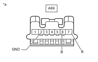
*a Front view of wire harness connector
(to Stop Light Switch Assembly)
Disconnect the stop light switch assembly connector.
-
Measure the voltage according to the value(s) in the table below.
Standard Voltage Tester Connection Condition Specified Condition A99-6 (B) - Body ground Ignition switch ON 11 to 14 V A99-7 (B) - Body ground Always 11 to 14 V -
Measure the resistance according to the value(s) in the table below.
Standard Resistance Tester Connection Condition Specified Condition A99-2 (GND) -Body ground Always Below 1 Ω Result Proceed to OK NG
OK
REPLACE STOP LIGHT SWITCH ASSEMBLY Click here
NG
REPAIR OR REPLACE HARNESS OR CONNECTOR
-
-
CHECK TERMINAL VOLTAGE (STP TERMINAL)
-
for Vacuum brake booster
-
Turn the ignition switch off.
-

*a Front view of wire harness connector
(to Skid Control ECU (Brake Actuator Assembly))
Disconnect the skid control ECU (brake actuator assembly) connector.
-
Measure the voltage according to the value(s) in the table below.
Standard Voltage Tester Connection Condition Specified Condition A6-2 (STP) - Body ground Brake pedal released Below 1.5 V
-
-
for Hydraulic brake booster
-
Turn the ignition switch off.
-
*a Front view of wire harness connector
(to Skid Control ECU (Master Cylinder Solenoid))
Disconnect the skid control ECU (master cylinder solenoid) connector.
-
Measure the voltage according to the value(s) in the table below.
Standard Voltage Tester Connection Condition Specified Condition A7-7 (STP) - Body ground Brake pedal released Below 1.5 V
Result Proceed to OK NG -
NG
CHECK HARNESS AND CONNECTOR (SKID CONTROL ECU - STOP LIGHT SWITCH ASSEMBLY) Click here
OK
-
-
CHECK HARNESS AND CONNECTOR (SKID CONTROL ECU - REAR COMBINATION LIGHT ASSEMBLY LH)
-
for Vacuum Brake Booster
-
Turn the ignition switch off.
-
Disconnect the A6 skid control ECU (brake actuator assembly) connector.
-
Disconnect the R22 rear combination light assembly LH connector.
-
Measure the voltage according to the value(s) in the table below.
Standard Voltage Tester Connection Condition Specified Condition A6-2 (STP) - Body ground Brake pedal depressed 11 to 14 V
-
-
for Hydraulic Brake Booster
-
Turn the ignition switch off.
-
Disconnect the A7 skid control ECU (master cylinder solenoid) connector.
-
Disconnect the R22 rear combination light assembly LH connector.
-
Measure the voltage according to the value(s) in the table below.
Standard Voltage Tester Connection Condition Specified Condition A7-7 (STP) - Body ground Brake pedal depressed 11 to 14 V
Result Proceed to OK NG -
OK
REPLACE REAR COMBINATION LIGHT ASSEMBLY LH Click here
NG
-
-
CHECK HARNESS AND CONNECTOR (SKID CONTROL ECU - REAR COMBINATION LIGHT ASSEMBLY RH)
-
for Vacuum Brake Booster
-
Turn the ignition switch off.
-
Disconnect the A6 skid control ECU (brake actuator assembly) connector.
-
Disconnect the R22 rear combination light assembly LH connector.
-
Disconnect the Q31*1 or R21*2 rear combination light assembly RH connector.
-
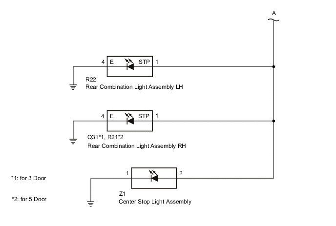
*1: for 3 Door
-
*2: for 5 Door
-
-
Measure the voltage according to the value(s) in the table below.
Standard Voltage Tester Connection Condition Specified Condition A6-2 (STP) - Body ground Brake pedal depressed 11 to 14 V
-
-
for Hydraulic Brake Booster
-
Turn the ignition switch off.
-
Disconnect the A7 skid control ECU (master cylinder solenoid) connector.
-
Disconnect the R22 rear combination light assembly LH connector.
-
Disconnect the Q31*1 or R21*2 rear combination light assembly RH connector.
-
*1: for 3 Door
-
*2: for 5 Door
-
-
Measure the voltage according to the value(s) in the table below.
Standard Voltage Tester Connection Condition Specified Condition A7-7 (STP) - Body ground Brake pedal depressed 11 to 14 V
Result Proceed to OK NG -
OK
REPLACE REAR COMBINATION LIGHT ASSEMBLY RH Click here
NG
-
-
CHECK HARNESS AND CONNECTOR (SKID CONTROL ECU - CENTER STOP LIGHT ASSEMBLY)
-
for Vacuum Brake Booster
-
Turn the ignition switch off.
-
Disconnect the A6 skid control ECU (brake actuator assembly) connector.
-
Disconnect the R22 rear combination light assembly LH connector.
-
Disconnect the Q31*1 or R21*2 rear combination light assembly RH connector.
-
*1: for 3 Door
-
*2: for 5 Door
-
-
Disconnect the Z1 center stop light assembly connector.
-
Measure the voltage according to the value(s) in the table below.
Standard Voltage Tester Connection Condition Specified Condition A6-2 (STP) - Body ground Brake pedal depressed 11 to 14 V
-
-
for Hydraulic Brake Booster
-
Turn the ignition switch off.
-
Disconnect the A7 skid control ECU (master cylinder solenoid) connector.
-
Disconnect the R22 rear combination light assembly LH connector.
-
Disconnect the Q31*1 or R21*2 rear combination light assembly RH connector.
-
*1: for 3 Door
-
*2: for 5 Door
-
-
Disconnect the Z1 center stop light assembly connector.
-
Measure the voltage according to the value(s) in the table below.
Standard Voltage Tester Connection Condition Specified Condition A7-7 (STP) - Body ground Brake pedal depressed 11 to 14 V
Result Proceed to OK NG -
OK
REPLACE CENTER STOP LIGHT ASSEMBLY Click here
NG
-
-
CHECK HARNESS AND CONNECTOR (SKID CONTROL ECU - STOP LIGHT SWITCH ASSEMBLY)
-
for Vacuum Brake Booster
-
Turn the ignition switch off.
-
Disconnect the A6 skid control ECU (brake actuator assembly) connector.
-
Disconnect the R22 rear combination light assembly LH connector.
-
Disconnect the Q31*1 or R21*2 rear combination light assembly RH connector.
-
*1: for 3 Door
-
*2: for 5 Door
-
-
Disconnect the Z1 center stop light assembly connector.
-
Disconnect the A99 stop light switch assembly connector.
-
Measure the resistance according to the value(s) in the table below.
Standard Resistance Tester Connection Condition Specified Condition A99-1 (OUT) - A6-2 (STP) Always Below 1 Ω A99-1 (OUT) or A6-2 (STP) - Body ground Always 10 kΩ or higher
-
-
for Hydraulic Brake Booster
-
Turn the ignition switch off.
-
Disconnect the A7 skid control ECU (master cylinder solenoid) connector.
-
Disconnect the R22 rear combination light assembly LH connector.
-
Disconnect the Q31*1 or R21*2 rear combination light assembly RH connector.
-
*1: for 3 Door
-
*2: for 5 Door
-
-
Disconnect the Z1 center stop light assembly connector.
-
Disconnect the A99 stop light switch assembly connector.
-
Measure the resistance according to the value(s) in the table below.
Standard Resistance Tester Connection Condition Specified Condition A99-1 (OUT) - A7-7 (STP) Always Below 1 Ω A99-1 (OUT) or A7-7 (STP) - Body ground Always 10 kΩ or higher
Result Proceed to OK NG -
OK
REPLACE STOP LIGHT SWITCH ASSEMBLY Click here
NG
REPAIR OR REPLACE HARNESS OR CONNECTOR
-
-
CHECK HARNESS AND CONNECTOR (SKID CONTROL ECU - STOP LIGHT SWITCH ASSEMBLY)
-
for Vacuum Brake Booster
-
Turn the ignition switch off.
-
Disconnect the A6 skid control ECU (brake actuator assembly) connector.
-
Disconnect the A99 stop light switch assembly connector.
-
Measure the voltage according to the value(s) in the table below.
Standard Voltage Tester Connection Condition Specified Condition A6-2 (STP) - Body ground Brake pedal released Below 1.5 V
-
-
for Hydraulic Brake Booster
-
Turn the ignition switch off.
-
Disconnect the A7 skid control ECU (master cylinder solenoid) connector.
-
Disconnect the A99 stop light switch assembly connector.
-
Measure the voltage according to the value(s) in the table below.
Standard Voltage Tester Connection Condition Specified Condition A7-7 (STP) - Body ground Brake pedal released Below 1.5 V
Result Proceed to OK NG -
OK
REPLACE STOP LIGHT SWITCH ASSEMBLY Click here
NG
-
-
CHECK HARNESS AND CONNECTOR (SKID CONTROL ECU - REAR COMBINATION LIGHT ASSEMBLY LH)
-
for Vacuum Brake Booster
-
Turn the ignition switch off.
-
Disconnect the A6 skid control ECU (brake actuator assembly) connector.
-
Disconnect the A99 stop light switch assembly connector.
-
Disconnect the R22 rear combination light assembly LH connector.
-
Measure the voltage according to the value(s) in the table below.
Standard Voltage Tester Connection Condition Specified Condition A6-2 (STP) - Body ground Brake pedal released Below 1.5 V
-
-
for Hydraulic Brake Booster
-
Turn the ignition switch off.
-
Disconnect the A7 skid control ECU (master cylinder solenoid) connector.
-
Disconnect the A99 stop light switch assembly connector.
-
Disconnect the R22 rear combination light assembly LH connector.
-
Measure the voltage according to the value(s) in the table below.
Standard Voltage Tester Connection Condition Specified Condition A7-7 (STP) - Body ground Brake pedal released Below 1.5 V
Result Proceed to OK NG -
OK
REPLACE REAR COMBINATION LIGHT ASSEMBLY LH Click here
NG
-
-
CHECK HARNESS AND CONNECTOR (SKID CONTROL ECU - REAR COMBINATION LIGHT ASSEMBLY RH)
-
for Vacuum Brake Booster
-
Turn the ignition switch off.
-
Disconnect the A6 skid control ECU (brake actuator assembly) connector.
-
Disconnect the A99 stop light switch assembly connector.
-
Disconnect the R22 rear combination light assembly LH connector.
-
Disconnect the Q31*1 or R21*2 rear combination light assembly RH connector.
-
*1: for 3 Door
-
*2: for 5 Door
-
-
Measure the voltage according to the value(s) in the table below.
Standard Voltage Tester Connection Condition Specified Condition A6-2 (STP) - Body ground Brake pedal released Below 1.5 V
-
-
for Hydraulic Brake Booster
-
Turn the ignition switch off.
-
Disconnect the A7 skid control ECU (master cylinder solenoid) connector.
-
Disconnect the A99 stop light switch assembly connector.
-
Disconnect the R22 rear combination light assembly LH connector.
-
Disconnect the Q31*1 or R21*2 rear combination light assembly RH connector.
-
*1: for 3 Door
-
*2: for 5 Door
-
-
Measure the voltage according to the value(s) in the table below.
Standard Voltage Tester Connection Condition Specified Condition A7-7 (STP) - Body ground Brake pedal released Below 1.5 V
Result Proceed to OK NG -
OK
REPLACE REAR COMBINATION LIGHT ASSEMBLY RH Click here
NG
-
-
CHECK HARNESS AND CONNECTOR (SKID CONTROL ECU - CENTER STOP LIGHT ASSEMBLY)
-
for Vacuum Brake Booster
-
Turn the ignition switch off.
-
Disconnect the A6 skid control ECU (brake actuator assembly) connector.
-
Disconnect the A99 stop light switch assembly connector.
-
Disconnect the R22 rear combination light assembly LH connector.
-
Disconnect the Q31*1 or R21*2 rear combination light assembly RH connector.
-
*1: for 3 Door
-
*2: for 5 Door
-
-
Disconnect the Z1 center stop light assembly connector.
-
Measure the voltage according to the value(s) in the table below.
Standard Voltage Tester Connection Condition Specified Condition A6-2 (STP) - Body ground Brake pedal released Below 1.5 V
-
-
for Hydraulic Brake Booster
-
Turn the ignition switch off.
-
Disconnect the A7 skid control ECU (master cylinder solenoid) connector.
-
Disconnect the A99 stop light switch assembly connector.
-
Disconnect the R22 rear combination light assembly LH connector.
-
Disconnect the Q31*1 or R21*2 rear combination light assembly RH connector.
-
*1: for 3 Door
-
*2: for 5 Door
-
-
Disconnect the Z1 center stop light assembly connector.
-
Measure the voltage according to the value(s) in the table below.
Standard Voltage Tester Connection Condition Specified Condition A7-7 (STP) - Body ground Brake pedal released Below 1.5 V
Result Proceed to OK NG -
OK
REPLACE CENTER STOP LIGHT ASSEMBLY Click here
NG
REPAIR OR REPLACE HARNESS OR CONNECTOR
-
-
CHECK HARNESS AND CONNECTOR (SKID CONTROL ECU - STOP LIGHT SWITCH ASSEMBLY)
-
for Vacuum Brake Booster
-
Turn the ignition switch off.
-
Disconnect the A6 skid control ECU (brake actuator assembly) connector.
-
Disconnect the A99 stop light switch assembly connector.
-
Measure the resistance according to the value(s) in the table below.
Standard Resistance Tester Connection Condition Specified Condition A6-31 (STPO) or A99-4 (ACC) - Body ground Always 10 kΩ or higher
-
-
for Hydraulic Brake Booster
-
Turn the ignition switch off.
-
Disconnect the A7 skid control ECU (master cylinder solenoid) connector.
-
Disconnect the A99 stop light switch assembly connector.
-
Measure the resistance according to the value(s) in the table below.
Standard Resistance Tester Connection Condition Specified Condition A7-16 (STPO) or A99-4 (ACC) - Body ground Always 10 kΩ or higher
Result Proceed to OK NG -
OK
REPLACE STOP LIGHT SWITCH ASSEMBLY Click here
NG
REPAIR OR REPLACE HARNESS OR CONNECTOR
-