CRUISE CONTROL SYSTEM TERMINALS OF ECM
-
CHECK ECM (for 1GR-FE)

-
Disconnect the C36, G55 and G56 ECM connectors.
-
Measure the voltage and resistance according to the value(s) in the table below.
Terminal No. (Symbol) Wiring Color Terminal Description Condition Specified Condition G55-24 (BATT) - Body ground L - Body ground Power source circuit Always 11 to 14 V G55-21 (IGSW) - Body ground*1
G56-21 (IGSW) - Body ground*2
W - Body ground IG power source circuit Ignition switch ON 11 to 14 V Ignition switch off Below 1 V G56-34 (ST1-) - Body ground*1
G55-8 (ST1-) - Body ground*2
B - Body ground Stop light switch signal circuit Ignition switch ON, brake pedal released 11 to 14 V Ignition switch ON, brake pedal depressed Below 1 V G56-35 (STP) - Body ground*1
G56-18 (STP) - Body ground*2
V - Body ground Stop light switch signal circuit Brake pedal depressed 11 to 14 V Brake pedal released Below 1 V G56-1 (CCS) - Body ground*1
G56-11 (CCS) - Body ground*2
B - Body ground Cruise control main switch circuit Cruise control main switch on Below 2.5 Ω Cruise control main switch off 10 kΩ or higher +RES switch held on 235 to 245 Ω -SET switch held on 617 to 643 Ω CANCEL switch held on 1509 to 1571 Ω C36-12 (E1) - Body ground BR - Body ground Ground Always Below 1 Ω
-
*1: for Automatic Transmission
-
*2: for Manual Transmission
-
-
Reconnect the C36, G55 and G56 ECM connectors.
-
Measure the voltage according to the value(s) in the table below.
Terminal No. (Symbol) Wiring Color Terminal Description Condition Specified Condition G56-22 (S) - Body ground*1 V - Body ground Transmission control switch circuit Ignition switch ON, shift lever in S 11 to 14 V Ignition switch ON, shift lever not in S Below 1 V G56-16 (SFTU) - Body ground*1 GR - Body ground Transmission control switch circuit Ignition switch ON, shift lever in S → shift lever moved to "+" 11 to 14 V → Below 1 V G56-9 (SFTD) - Body ground*1 LG - Body ground Transmission control switch circuit Ignition switch ON, shift lever in S → shift lever moved to "-" 11 to 14 V → Below 1 V C34-22 (D) - Body ground*1 B - Body ground Park/neutral position switch signal Ignition switch ON, shift lever in D 11 to 14 V Ignition switch ON, shift lever not in D Below 1 V C34-27 (D) - Body ground*2 B - Body ground Clutch switch circuit Ignition switch ON, clutch pedal depressed 11 to 14 V Ignition switch ON, clutch pedal released Below 1 V C34-27 (P) - Body ground*1 L - Body ground Park/neutral position switch signal Ignition switch ON, shift lever in P 11 to 14 V Ignition switch ON, shift lever not in P Below 1 V C34-28 (R) - Body ground*1 R - Body ground Park/neutral position switch signal Ignition switch ON, shift lever in R 11 to 14 V Ignition switch ON, shift lever not in R Below 1 V C34-21 (N) - Body ground*1 G - Body ground Park/neutral position switch signal Ignition switch ON, shift lever in N 11 to 14 V Ignition switch ON, shift lever not in N Below 1 V
-
*1: for Automatic Transmission
-
*2: for Manual Transmission
-
-
-
CHECK ECM (for 2TR-FE)
-
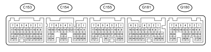
Disconnect the C153, G180 and G181 ECM connectors.
-
Measure the voltage and resistance according to the value(s) in the table below.
Terminal No. (Symbol) Wiring Color Terminal Description Condition Specified Condition G180-3 (BATT) - Body ground L - Body ground Power source circuit Always 11 to 14 V G180-8 (IGSW) - Body ground W - Body ground IG power source circuit Ignition switch ON 11 to 14 V Ignition switch off Below 1 V G180-11 (ST1-) - Body ground B - Body ground Stop light switch signal circuit Ignition switch ON, brake pedal released 11 to 14 V Ignition switch ON, brake pedal depressed Below 1 V G180-10 (STP) - Body ground V - Body ground Stop light switch signal circuit Brake pedal depressed 11 to 14 V Brake pedal released Below 1 V G181-22 (CCS) - Body ground B - Body ground Cruise control main switch circuit Cruise control main switch on Below 2.5 Ω Cruise control main switch off 10 kΩ or higher +RES switch held on 235 to 245 Ω -SET switch held on 617 to 643 Ω CANCEL switch held on 1509 to 1571 Ω C153-3 (E1) - Body ground BR - Body ground Ground Always Below 1 Ω -
Reconnect the C153, G180 and G181 ECM connectors.
-
Measure the voltage according to the value(s) in the table below.
Terminal No. (Symbol) Wiring Color Terminal Description Condition Specified Condition G181-18 (D) - Body ground B - Body ground Park/neutral position switch signal Ignition switch ON, shift lever in D 11 to 14 V Ignition switch ON, shift lever not in D Below 1 V C155-25 (P) - Body ground L - Body ground Park/neutral position switch signal Ignition switch ON, shift lever in P 11 to 14 V Ignition switch ON, shift lever not in P Below 1 V G181-8 (R) - Body ground R - Body ground Park/neutral position switch signal Ignition switch ON, shift lever in R 11 to 14 V Ignition switch ON, shift lever not in R Below 1 V C155-24 (N) - Body ground G - Body ground Park/neutral position switch signal Ignition switch ON, shift lever in N 11 to 14 V Ignition switch ON, shift lever not in N Below 1 V
-
-
CHECK ECM (for 1KD-FTV)
-
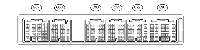
Disconnect the C93, G57 and G58 ECM connectors.
-
Measure the voltage and resistance according to the value(s) in the table below.
Terminal No. (Symbol) Wiring Color Terminal Description Condition Specified Condition G57-23 (BATT) - Body ground L - Body ground Power source circuit Always 11 to 14 V G58-24 (IGSW) - Body ground W - Body ground IG power source circuit Ignition switch ON 11 to 14 V Ignition switch off Below 1 V G57-9 (ST1-) - Body ground B - Body ground Stop light switch signal circuit Ignition switch ON, brake pedal released 11 to 14 V Ignition switch ON, brake pedal depressed Below 1 V G57-8 (STP) - Body ground V - Body ground Stop light switch signal circuit Brake pedal depressed 11 to 14 V Brake pedal released Below 1 V G57-14 (CCS) - Body ground B - Body ground Cruise control main switch circuit Cruise control main switch on Below 2.5 Ω Cruise control main switch off 10 kΩ or higher +RES switch held on 235 to 245 Ω -SET switch held on 617 to 643 Ω CANCEL switch held on 1509 to 1571 Ω C93-1 (E1) - Body ground BR - Body ground Ground Always Below 1 Ω -
Reconnect the C93, G57 and G58 ECM connectors.
-
Measure the voltage according to the value(s) in the table below.
Terminal No. (Symbol) Wiring Color Terminal Description Condition Specified Condition C91-15 (CLSW) - Body ground*1 B - Body ground Park/neutral position switch signal Ignition switch ON, shift lever in D 11 to 14 V Ignition switch ON, shift lever not in D Below 1 V C91-15 (D) - Body ground*2 G - Body ground Clutch switch circuit Ignition switch ON, clutch pedal depressed 11 to 14 V Ignition switch ON, clutch pedal released Below 1 V
-
*1: for Automatic Transmission
-
*2: for Manual Transmission
-
-
-
CHECK TRANSMISSION CONTROL ECU (for 1KD-FTV and Automatic Transmission)
-
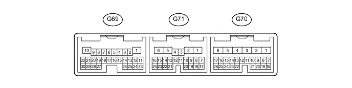
Disconnect the G70 and G69 ECU connectors.
-
Measure the voltage and resistance according to the value(s) in the table below.
Terminal No. (Symbol) Wiring Color Terminal Description Condition Specified Condition G70-5 (BATT) - Body ground L - Body ground Power source circuit Always 11 to 14 V G70-6 (IG2) - Body ground B - Body ground IG power source circuit Ignition switch ON 11 to 14 V Ignition switch off Below 1 V G69-1 (E1) - Body ground BR - Body ground Ground Always Below 1 Ω G69-10 (E01) - Body ground W-B - Body ground Ground Always Below 1 Ω -
Reconnect the G70 and G69 ECU connector.
-
Measure the voltage according to the value(s) in the table below.
Terminal No. (Symbol) Wiring Color Terminal Description Condition Specified Condition G70-15 (S) - Body ground V - Body ground Transmission control switch circuit Ignition switch ON, shift lever in S 11 to 14 V Ignition switch ON, shift lever not in S Below 1 V G70-22 (SFTU) - Body ground GR - Body ground Transmission control switch circuit Ignition switch ON, shift lever in S → shift lever moved to "+" 11 to 14 V → Below 1 V G70-23 (SFTD) - Body ground LG - Body ground Transmission control switch circuit Ignition switch ON, shift lever in S → shift lever moved to "-" 11 to 14 V → Below 1 V G71-8 (D) - Body ground B - Body ground Park/neutral position switch signal Ignition switch ON, shift lever in D 11 to 14 V Ignition switch ON, shift lever not in D Below 1 V G69-13 (P) - Body ground L - Body ground Park/neutral position switch signal Ignition switch ON, shift lever in P 11 to 14 V Ignition switch ON, shift lever not in P Below 1 V G71-9 (R) - Body ground R - Body ground Park/neutral position switch signal Ignition switch ON, shift lever in R 11 to 14 V Ignition switch ON, shift lever not in R Below 1 V G69-14 (N) - Body ground G - Body ground Park/neutral position switch signal Ignition switch ON, shift lever in N 11 to 14 V Ignition switch ON, shift lever not in N Below 1 V
-
-
CHECK ECM (for 1GD-FTV)
-
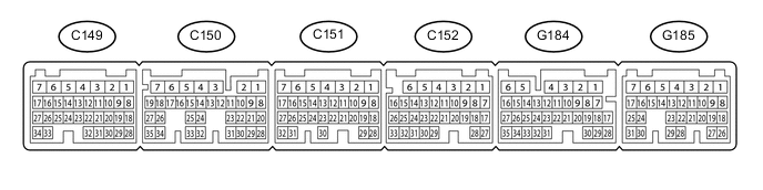
Disconnect the G185 and C152 ECM connectors.
-
Measure the voltage and resistance according to the value(s) in the table below.
Terminal No. (Symbol) Wiring Color Terminal Description Condition Specified Condition G185-1 (BATT) - Body ground L - Body ground Power source circuit Always 11 to 14 V G185-18 (IGSW) - Body ground W - Body ground IG power source circuit Ignition switch ON 11 to 14 V Ignition switch off Below 1 V G185-12 (ST1-) - Body ground B - Body ground Stop light switch signal circuit Ignition switch ON, brake pedal released 11 to 14 V Ignition switch ON, brake pedal depressed Below 1 V G185-13 (STP) - Body ground V - Body ground Stop light switch signal circuit Brake pedal depressed 11 to 14 V Brake pedal released Below 1 V G185-26 (CCS) - Body ground B - Body ground Cruise control main switch circuit Cruise control main switch on Below 2.5 Ω Cruise control main switch off 10 kΩ or higher +RES switch held on 235 to 245 Ω -SET switch held on 617 to 643 Ω CANCEL switch held on 1509 to 1571 Ω C152-1 (E1) - Body ground W-B - Body ground Ground Always Below 1 Ω -
Reconnect the G185 and C152 ECM connectors.
-
Measure the voltage according to the value(s) in the table below.
Terminal No. (Symbol) Wiring Color Terminal Description Condition Specified Condition G184-13 (S) - Body ground*1 V - Body ground Transmission control switch circuit Ignition switch ON, shift lever in S 11 to 14 V Ignition switch ON, shift lever not in S Below 1 V G184-21 (SFTU) - Body ground*1 GR - Body ground Transmission control switch circuit Ignition switch ON, shift lever in S → shift lever moved to "+" 11 to 14 V → Below 1 V G184-20 (SFTD) - Body ground*1 LG - Body ground Transmission control switch circuit Ignition switch ON, shift lever in S → shift lever moved to "-" 11 to 14 V → Below 1 V C149-14 (D) - Body ground*1 B - Body ground Park/neutral position switch signal Ignition switch ON, shift lever in D 11 to 14 V Ignition switch ON, shift lever not in D Below 1 V C149-14 (D) - Body ground*2 B - Body ground Clutch switch circuit Ignition switch ON, clutch pedal depressed 11 to 14 V Ignition switch ON, clutch pedal released Below 1 V C149-12 (P) - Body ground*1 L - Body ground Park/neutral position switch signal Ignition switch ON, shift lever in P 11 to 14 V Ignition switch ON, shift lever not in P Below 1 V C149-15 (R) - Body ground*1 R - Body ground Park/neutral position switch signal Ignition switch ON, shift lever in R 11 to 14 V Ignition switch ON, shift lever not in R Below 1 V C149-13 (N) - Body ground*1 G - Body ground Park/neutral position switch signal Ignition switch ON, shift lever in N 11 to 14 V Ignition switch ON, shift lever not in N Below 1 V
-
*1: for Automatic Transmission
-
*2: for Manual Transmission
-
-