LIGHTING SYSTEM(except 5L-E) Door Mirror Foot Light Circuit
DESCRIPTION
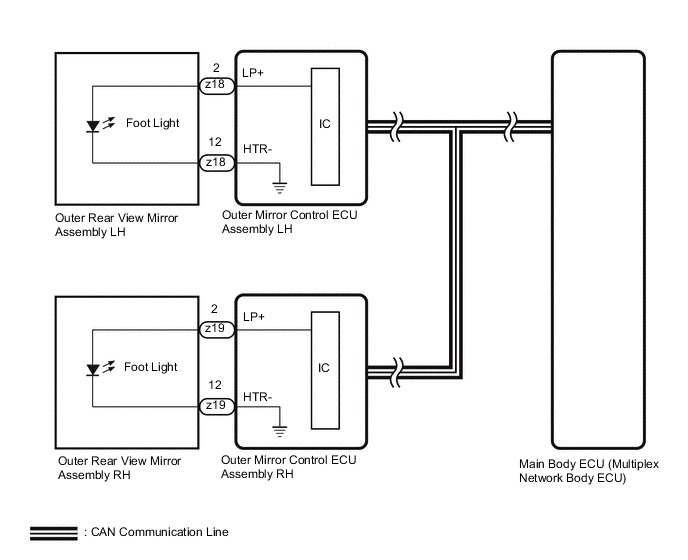
The outer mirror control ECU assembly controls the outer rear view mirror assembly (foot lights).
WIRING DIAGRAM
PROCEDURE
-
CHECK FOOT LIGHTS
-
Check the illumination of each foot lights.
Result Result Proceed to Foot light LH does not illuminate. A Foot light RH does not illuminate. B
B 
PERFORM ACTIVE TEST USING GTS Click here
A 
-
-
PERFORM ACTIVE TEST USING GTS
-
Perform the Active Test according to the display on the GTS.
Mirror L Tester Display Test Part Control Range Diagnostic Note Fr Foot Light Outer rear view mirror assembly LH (foot light LH) OFF or ON - OK Foot light LH turn on. Result Proceed to OK NG
OK 
PROCEED TO NEXT SUSPECTED AREA SHOWN IN PROBLEM SYMPTOMS TABLE Click here
NG
-
-
INSPECT OUTER REAR VIEW MIRROR ASSEMBLY LH
-
Remove the outer rear view mirror assembly LH.
-
Inspect the outer rear view mirror assembly LH.
Result Proceed to OK NG
OK
REPLACE OUTER MIRROR CONTROL ECU ASSEMBLY LH Click here
NG
REPLACE OUTER REAR VIEW MIRROR ASSEMBLY LH Click here
-
-
PERFORM ACTIVE TEST USING GTS
-
Perform the Active Test according to the display on the GTS.
Mirror R Tester Display Test Part Control Range Diagnostic Note Fr Foot Light Outer rear view mirror assembly RH (foot light RH) OFF or ON - OK Foot light RH turn on. Result Proceed to OK NG
OK
PROCEED TO NEXT SUSPECTED AREA SHOWN IN PROBLEM SYMPTOMS TABLE Click here
NG
-
-
INSPECT OUTER REAR VIEW MIRROR ASSEMBLY RH
-
Remove the outer rear view mirror assembly RH.
-
Inspect the outer rear view mirror assembly RH.
Result Proceed to OK NG
OK
REPLACE OUTER MIRROR CONTROL ECU ASSEMBLY RH Click here
NG
REPLACE OUTER REAR VIEW MIRROR ASSEMBLY RH Click here
-