LIGHTING SYSTEM(except 5L-E) Step Illumination Circuit
DESCRIPTION
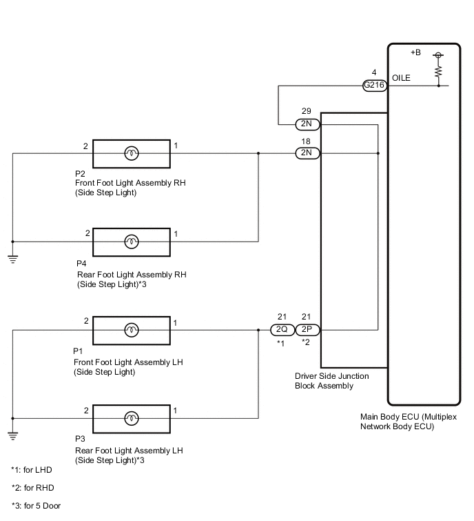
The main body ECU (multiplex network body ECU) controls the operation of the following lights:
-
Front foot light assembly LH (side step light)
-
Front foot light assembly RH (side step light)
-
Rear foot light assembly LH (side step light) (for 5 Door)
-
Rear foot light assembly RH (side step light) (for 5 Door)
WIRING DIAGRAM
CAUTION / NOTICE / HINT
Note
Before replacing the main body ECU (multiplex network body ECU), refer to Service Bulletin.
PROCEDURE
-
PERFORM ACTIVE TEST USING GTS
-
Perform the Active Test according to the display on the GTS.
Main Body Tester Display Measurement Item Control Range Diagnostic Note Step Light Foot light assembly (side step light) OFF or ON - OK Foot light assembly (side step light) turn on. Result Proceed to OK NG
OK 
PROCEED TO NEXT SUSPECTED AREA SHOWN IN PROBLEM SYMPTOMS TABLE Click here
NG 
-
-
CHECK HARNESS AND CONNECTOR (DRIVER SIDE JUNCTION BLOCK ASSEMBLY - MAIN BODY ECU [MULTIPLEX NETWORK BODY ECU])
-
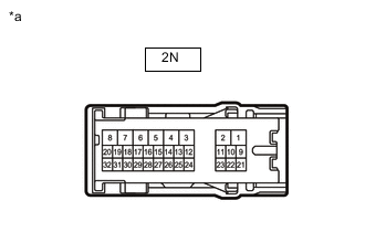
Disconnect the 2N driver side junction block assembly connector.
-
Disconnect the G216 main body ECU (multiplex network body ECU) connector.
-
Measure the resistance according to the value(s) in the table below.
Standard Resistance Tester Connection Condition Specified Condition 2N-29 - G216-4 (OILE) Always Below 1 Ω 2N-29 or G216-4 (OILE) - Body ground Always 10 kΩ or higher Result Proceed to OK NG
NG
REPAIR OR REPLACE HARNESS OR CONNECTOR
OK
-
-
CHECK DRIVER SIDE JUNCTION BLOCK ASSEMBLY
-
*a Component without harness connected
(Driver Side Junction Block Assembly)
Remove the driver side junction block assembly.
-
Remove the main body ECU (multiplex network body ECU) from the driver side junction block assembly.
-
Measure the resistance according to the value(s) in the table below.
Standard Resistance Tester Connection Condition Specified Condition 2N-18 - 2N-29 Always Below 1 Ω Result Proceed to OK NG
OK
REPLACE MAIN BODY ECU (MULTIPLEX NETWORK BODY ECU) Click here
NG
REPLACE DRIVER SIDE JUNCTION BLOCK ASSEMBLY Click here
-