LIGHTING SYSTEM(except 5L-E) Overhead Console Illumination Light Circuit
DESCRIPTION
The main body ECU (multiplex network body ECU) controls the operation of the map light assembly (shift lever illumination).
WIRING DIAGRAM
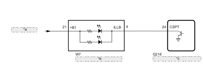
| *a | from DOME Relay |
| *b | Map Light Assembly (Shift Lever Illumination) |
| *c | Main Body ECU (Multiplex Network Body ECU) |
CAUTION / NOTICE / HINT
Note
Before replacing the main body ECU (multiplex network body ECU), refer to Service Bulletin.
PROCEDURE
-
PERFORM ACTIVE TEST USING GTS
-
Perform the Active Test according to the display on the GTS.
Main Body Tester Display Measurement Item Control Range Diagnostic Note Cent Consol Spot LGT Map light assembly (shift lever illumination) OFF or ON - OK Map light assembly (shift lever illumination) turn on. Result Proceed to OK NG
OK 
PROCEED TO NEXT SUSPECTED AREA SHOWN IN PROBLEM SYMPTOMS TABLE Click here
NG 
-
-
INSPECT MAP LIGHT ASSEMBLY
-
Remove the map light assembly.
-
Apply battery voltage to the connector and check the light illumination condition.
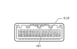
OK Battery Connection Specified Condition Positive (+) → 21 (+B1)
Negative (-) → 4 (ILLB)
Map light assembly (shift lever illumination) illuminates Result Proceed to OK NG
NG
REPLACE MAP LIGHT ASSEMBLY Click here
OK
-
-
CHECK HARNESS AND CONNECTOR (MAP LIGHT ASSEMBLY - MAIN BODY ECU [MULTIPLEX NETWORK BODY ECU])
-
Disconnect the W7 map light assembly (shift lever illumination) connector.
-
Disconnect the G216 main body ECU (multiplex network body ECU) connector.
-
Measure the resistance according to the value(s) in the table below.
Standard Resistance Tester Connection Condition Specified Condition W7-4 (ILLB) - G216-24 (CSPT) Always Below 1 Ω W7-4 (ILLB) or G216-24 (CSPT) - Body ground Always 10 kΩ or higher Result Proceed to OK NG
OK
REPLACE MAIN BODY ECU (MULTIPLEX NETWORK BODY ECU) Click here
NG
REPAIR OR REPLACE HARNESS OR CONNECTOR
-