LIGHTING SYSTEM(except 5L-E) Interior Light Switch Signal Circuit
DESCRIPTION
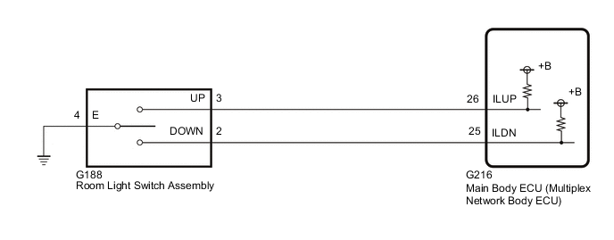
The main body ECU (multiplex network body ECU) detects the condition of the room light switch assembly.
WIRING DIAGRAM
CAUTION / NOTICE / HINT
Note
Before replacing the main body ECU (multiplex network body ECU), refer to Service Bulletin.
PROCEDURE
-
READ VALUE USING GTS
-
Read the Data List according to the display on the GTS.
Main Body Tester Display Measurement Item / Range Normal Condition Diagnostic Note Interior Lamp Brightness (Up) Room light switch assembly (Up switch) / OFF or ON OFF: Room light switch assembly (Up switch) off
ON: Room light switch assembly (Up switch) on
- Interior Lamp Brightness (Down) Room light switch assembly (Down switch) / OFF or ON OFF: Room light switch assembly (Down switch) off
ON: Room light switch assembly (Down switch) on
- OK Normal conditions listed above are displayed. Result Proceed to OK NG
OK 
PROCEED TO NEXT SUSPECTED AREA SHOWN IN PROBLEM SYMPTOMS TABLE
NG 
-
-
INSPECT ROOM LIGHT SWITCH ASSEMBLY
-
Remove the room light switch assembly.
-
Inspect the room light switch assembly.
Result Proceed to OK NG
NG
REPLACE ROOM LIGHT SWITCH ASSEMBLY Click here
OK
-
-
CHECK HARNESS AND CONNECTOR (ROOM LIGHT SWITCH ASSEMBLY - MAIN BODY ECU [MULTIPLEX NETWORK BODY ECU] AND BODY GROUND)
-
Disconnect the G188 room light switch assembly connector.
-
Disconnect the G216 main body ECU (multiplex network body ECU) connector.
-
Measure the resistance according to the value(s) in the table below.
Standard Resistance Tester Connection Condition Specified Condition G188-3 (UP) - G216-26 (ILUP) Always Below 1 Ω G188-2 (DOWN) - G216-25 (ILDN) Always Below 1 Ω G188-4 (E) - Body ground Always Below 1 Ω G188-3 (UP) or G216-26 (ILUP) - Body ground Always 10 kΩ or higher G188-2 (DOWN) or G216-25 (ILDN) - Body ground Always 10 kΩ or higher Result Proceed to OK NG
OK
REPLACE MAIN BODY ECU (MULTIPLEX NETWORK BODY ECU) Click here
NG
REPAIR OR REPLACE HARNESS OR CONNECTOR
-