LIGHTING SYSTEM(except 5L-E) Interior Light Auto Cut Circuit
DESCRIPTION
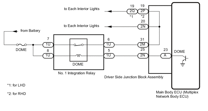
When the battery saving control operates, the main body ECU (multiplex network body ECU) controls the operation of the DOME relay that is built into the No. 1 integration relay to turn off the interior lights.
WIRING DIAGRAM
CAUTION / NOTICE / HINT
Note
Before replacing the main body ECU (multiplex network body ECU), refer to Service Bulletin.
PROCEDURE
-
PERFORM ACTIVE TEST USING GTS
-
All of the interior lights turn on.
-
Perform the Active Test according to the display on the GTS.
Main Body Tester Display Measurement Item Control Range Diagnostic Note Relay for Interior Light Auto Cut Function DOME relay OFF or ON OFF: DOME relay on (interior lights turn on)
ON: DOME relay off (interior lights turn off)
OK All of the interior lights turn off when ON is selected. Result Proceed to OK NG
OK 
PROCEED TO NEXT SUSPECTED AREA SHOWN IN PROBLEM SYMPTOMS TABLE Click here
NG 
-
-
INSPECT NO. 1 INTEGRATION RELAY
-
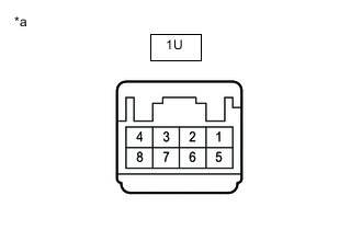
*a Component without harness connected
(No. 1 Integration Relay)
Remove the No. 1 integration relay.
-
Measure the resistance according to the value(s) in the table below.
Standard Resistance Tester Connection Condition Specified Condition 1U-6 - 1U-7 Battery not connected to 1U-5 and 1U-8 Below 1 Ω Battery positive (+) → 1U-8
Battery negative (-) → 1U-5
10 kΩ or higher Result Proceed to OK NG
NG
REPLACE NO. 1 INTEGRATION RELAY
OK
-
-
CHECK HARNESS AND CONNECTOR (NO. 1 INTEGRATION RELAY - DRIVER SIDE JUNCTION BLOCK ASSEMBLY AND BATTERY)
-
Remove the No. 1 integration relay.
-
Disconnect the 2M and 2N driver side junction block assembly connectors.
-
Measure the resistance according to the value(s) in the table below.
Standard Resistance Tester Connection Condition Specified Condition 1U-5 - 2N-25 Always Below 1 Ω 1U-6 - 2M-31 Always Below 1 Ω 1U-5 or 2N-25 - Body ground Always 10 kΩ or higher 1U-6 or 2M-31 - Body ground Always 10 kΩ or higher -
Measure the voltage according to the value(s) in the table below.
Standard Voltage Tester Connection Condition Specified Condition 1U-7 - Body ground Always 11 to 14 V 1U-8 - Body ground Always 11 to 14 V Result Proceed to OK NG
NG
REPAIR OR REPLACE HARNESS OR CONNECTOR
OK
-
-
CHECK DRIVER SIDE JUNCTION BLOCK ASSEMBLY
-
Remove the driver side junction block assembly.
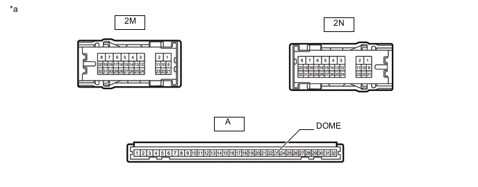
*a Component without harness connected
(Driver Side Junction Block Assembly)
- - -
Remove the main body ECU (multiplex network body ECU) from the driver side junction block assembly.
-
Measure the resistance according to the value(s) in the table below.
Standard Resistance Tester Connection Condition Specified Condition 2N-25 - A-23 (DOME) Always Below 1 Ω 2M-31 - 2N-20 Always Below 1 Ω Result Proceed to OK NG
OK
REPLACE MAIN BODY ECU (MULTIPLEX NETWORK BODY ECU) Click here
NG
REPLACE DRIVER SIDE JUNCTION BLOCK ASSEMBLY Click here
-