LIGHTING SYSTEM(except 5L-E) Interior Light Circuit
DESCRIPTION
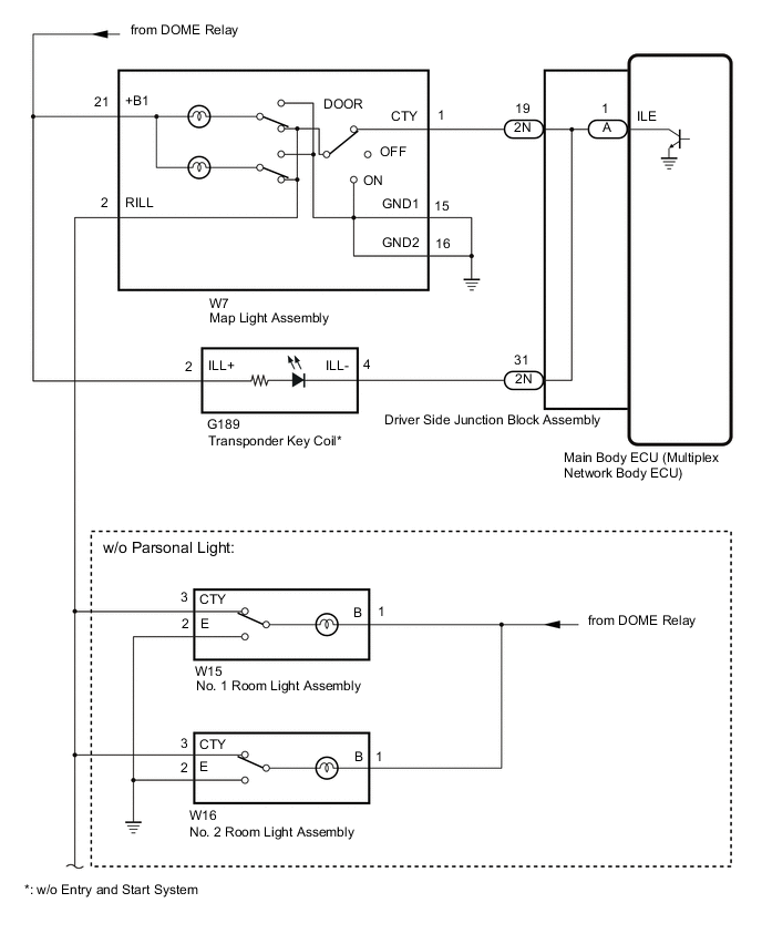
The main body ECU (multiplex network body ECU) controls the operation of the following lights:
-
Map light assembly
-
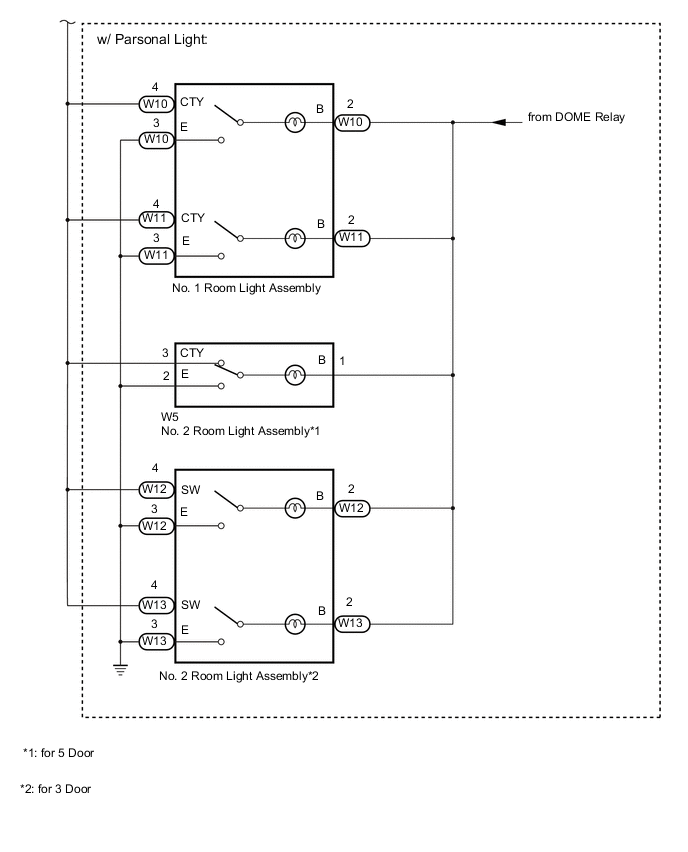
No. 1 room light assembly
-
No. 2 room light assembly
-
Transponder key coil (w/o Entry and Start System)
WIRING DIAGRAM
CAUTION / NOTICE / HINT
Note
Before replacing the main body ECU (multiplex network body ECU), refer to Service Bulletin.
PROCEDURE
-
PERFORM ACTIVE TEST USING GTS
-
Perform the Active Test according to the display on the GTS.
Main Body Tester Display Measurement Item Control Range Diagnostic Note Illuminated Entry System Map light assembly, transponder key coil*, No. 1 room light assembly and No. 2 room light assembly OFF or ON Turn the map light assembly, No. 1 room light assembly and No. 2 room light assembly to the DOOR position. *: w/o Entry and Start System
OK All lights illuminates. Result Proceed to OK NG
OK 
PROCEED TO NEXT SUSPECTED AREA SHOWN IN PROBLEM SYMPTOMS TABLE Click here
NG 
-
-
CHECK DRIVER SIDE JUNCTION BLOCK ASSEMBLY
-
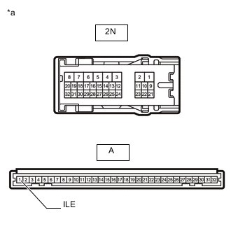
*a Component without harness connected
(Driver Side Junction Block Assembly)
Remove the driver side junction block assembly.
-
Remove the main body ECU (multiplex network body ECU) from the driver side junction block assembly.
-
Measure the resistance according to the value(s) in the table below.
Standard Resistance Tester Connection Condition Specified Condition 2N-19 - A-1 (ILE) Always Below 1 Ω 2N-31 - A-1 (ILE) Always Below 1 Ω Result Proceed to OK NG
OK
REPLACE MAIN BODY ECU (MULTIPLEX NETWORK BODY ECU) Click here
NG
REPLACE DRIVER SIDE JUNCTION BLOCK ASSEMBLY Click here
-