LIGHTING SYSTEM(except 5L-E) Door Illumination Circuit
DESCRIPTION
The main body ECU (multiplex network body ECU) controls the operation of the following lights:
-
No. 2 interior illumination light sub-assembly (door pocket light)
-
Door inside handle illumination light assembly
-
Door trim board sub-assembly (ornament illumination)
WIRING DIAGRAM

CAUTION / NOTICE / HINT
Note
Before replacing the main body ECU (multiplex network body ECU), refer to Service Bulletin.
PROCEDURE
-
CHECK DOOR ILLUMINATION LIGHTS
-
Check the illumination of each door illumination lights.
Result Result Proceed to Front door illumination light does not illuminate. A Rear door illumination light does not illuminate. (for 5 Door) B
B 
PERFORM ACTIVE TEST USING GTS Click here
A 
-
-
PERFORM ACTIVE TEST USING GTS
-
Perform the Active Test according to the display on the GTS.
Main Body Tester Display Measurement Item Control Range Diagnostic Note Interior Illumination Light1 Front door illumination lights OFF or ON - OK Front door illumination lights turn on. Result Proceed to OK NG
OK 
PROCEED TO NEXT SUSPECTED AREA SHOWN IN PROBLEM SYMPTOMS TABLE Click here
NG
-
-
CHECK HARNESS AND CONNECTOR (FRONT DOOR ILLUMINATION LIGHT CIRCUIT)
-
*: for 5 Door
-
Disconnect the k3 front door inside handle illumination light assembly LH connector.
-
Disconnect the j3 front door inside handle illumination light assembly RH connector.
-
Disconnect the k2 front door trim board sub-assembly LH (ornament illumination) connector.*
-
Disconnect the j2 front door trim board sub-assembly RH (ornament illumination) connector.*
-
Disconnect the k1 No. 2 interior illumination light sub-assembly LH (front door pocket light LH) connector.
-
Disconnect the j1 No. 2 interior illumination light sub-assembly RH (front door pocket light RH) connector.
-
Enter the following menus: Body Electrical / MainBody / Active Test / Control the DOME Relay.
Main Body Tester Display Measurement Item Control Range Diagnostic Note Relay for Interior Light Auto Cut Function DOME relay OFF or ON OFF: DOME relay on (interior lights turn on)
ON: DOME relay off (interior lights turn off)
-
Measure the voltage according to the value(s) in the table below.
Standard Voltage Tester Connection GTS Operation Specified Condition j1-2 (B) - Body ground Active Test is not performed (OFF) 11 to 14 V Active Test is performed (ON) Below 1 V -
Disconnect the G216 main body ECU (multiplex network body ECU) connector.
-
Measure the resistance according to the value(s) in the table below.
Standard Resistance Tester Connection Condition Specified Condition j1-1 (E) - G216-21 (LED1) Always Below 1 Ω j1-1 (E) or G216-21 (LED1) - Body ground Always 10 kΩ or higher Result Proceed to OK NG
OK
REPLACE MAIN BODY ECU (MULTIPLEX NETWORK BODY ECU) Click here
NG
REPAIR OR REPLACE HARNESS OR CONNECTOR
-
-
PERFORM ACTIVE TEST USING GTS
-
Perform the Active Test according to the display on the GTS.
Main Body Tester Display Measurement Item Control Range Diagnostic Note Interior Illumination Light2 Rear door illumination lights OFF or ON - OK Rear door illumination lights turn on. Result Proceed to OK NG
OK
PROCEED TO NEXT SUSPECTED AREA SHOWN IN PROBLEM SYMPTOMS TABLE Click here
NG
-
-
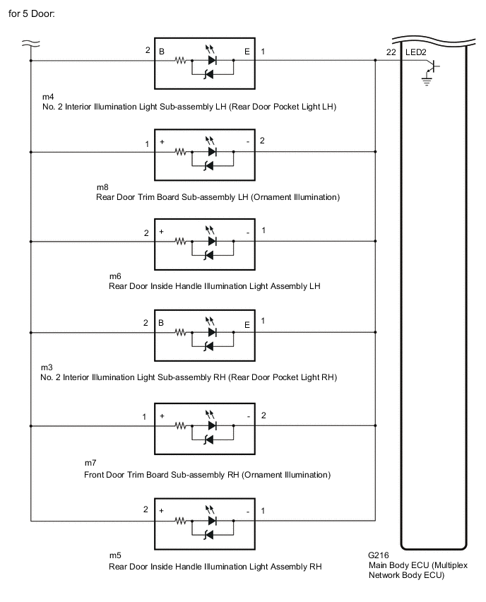
CHECK HARNESS AND CONNECTOR (REAR DOOR ILLUMINATION LIGHT CIRCUIT)
-
Disconnect the m6 rear door inside handle illumination light assembly LH connector.
-
Disconnect the m5 rear door inside handle illumination light assembly RH connector.
-
Disconnect the m8 rear door trim board sub-assembly LH (ornament illumination) connector.
-
Disconnect the m7 rear door trim board sub-assembly RH (ornament illumination) connector.
-
Disconnect the m4 No. 2 interior illumination light sub-assembly LH (rear door pocket light LH) connector.
-
Disconnect the m3 No. 2 interior illumination light sub-assembly RH (rear door pocket light RH) connector.
-
Enter the following menus: Body Electrical / MainBody / Active Test / Control the DOME Relay.
Main Body Tester Display Measurement Item Control Range Diagnostic Note Relay for Interior Light Auto Cut Function DOME relay OFF or ON OFF: DOME relay on (interior lights turn on)
ON: DOME relay off (interior lights turn off)
-
Measure the voltage according to the value(s) in the table below.
Standard Voltage Tester Connection GTS Operation Specified Condition m3-2 (B) - Body ground Active Test is not performed (OFF) 11 to 14 V Active Test is performed (ON) Below 1 V -
Disconnect the G216 main body ECU (multiplex network body ECU) connector.
-
Measure the resistance according to the value(s) in the table below.
Standard Resistance Tester Connection Condition Specified Condition m3-1 (E) - G216-22 (LED2) Always Below 1 Ω m3-1 (E) or G216-22 (LED2) - Body ground Always 10 kΩ or higher Result Proceed to OK NG
OK
REPLACE MAIN BODY ECU (MULTIPLEX NETWORK BODY ECU) Click here
NG
REPAIR OR REPLACE HARNESS OR CONNECTOR
-