LIGHTING SYSTEM(except 5L-E) TERMINALS OF ECU
-
CHECK DRIVER SIDE JUNCTION BLOCK ASSEMBLY, MAIN BODY ECU (MULTIPLEX NETWORK BODY ECU)
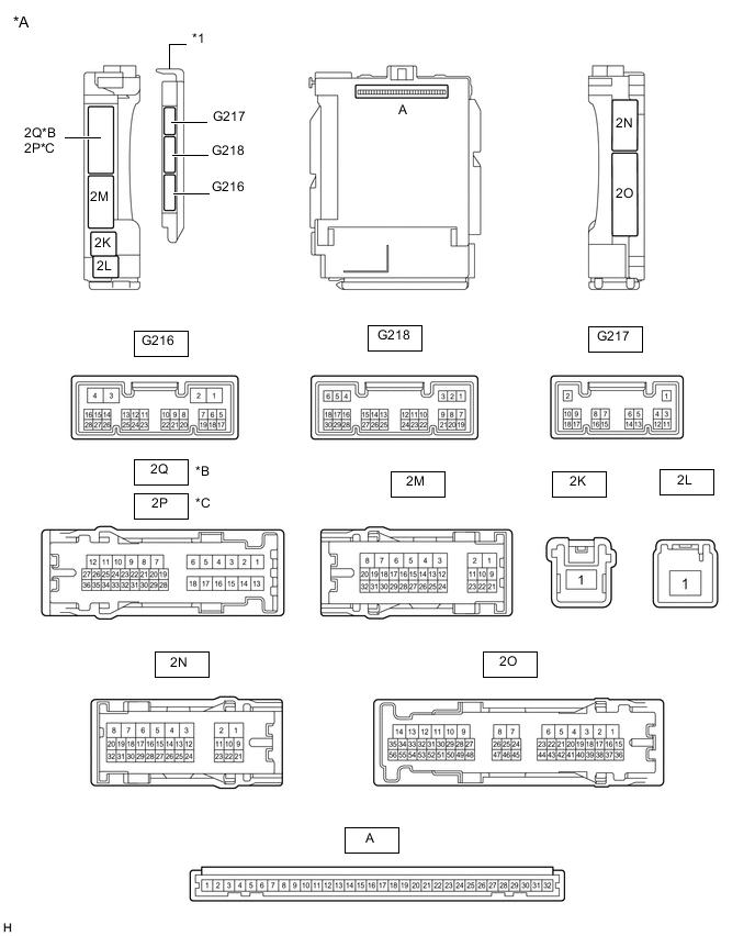
*A Main Body ECU (Multiplex Network Body ECU) with 3 connectors *B for LHD *C for RHD - - *1 Main Body ECU (Multiplex Network Body ECU) - - 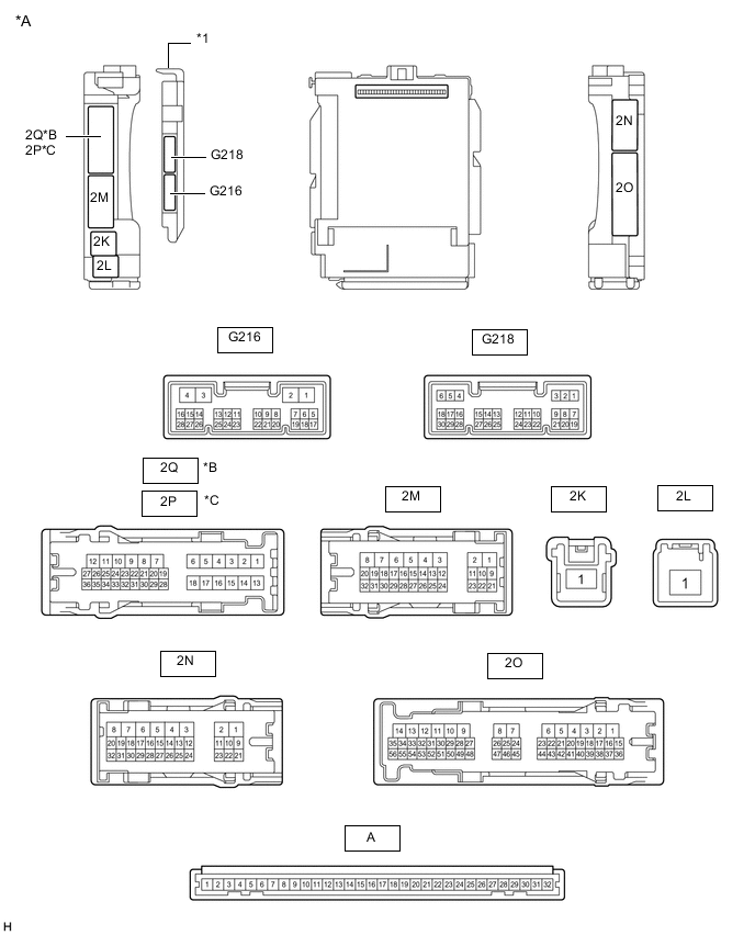
*A Main Body ECU (Multiplex Network Body ECU) with 2 connectors *B for LHD *C for RHD - - *1 Main Body ECU (Multiplex Network Body ECU) - -
-
Remove the main body ECU (multiplex network body ECU) from the driver side junction block assembly.
-
Connect the driver side junction block assembly connectors.
-
Measure the voltage and resistance according to the value(s) in the table below.
Terminal No. (Symbol) Wiring Color Terminal Description Condition Specified Condition A-32 (IG) - Body ground None - Body ground Ignition power supply Ignition switch ON 11 to 14 V Ignition switch off Below 1 V A-31 (BECU) - Body ground None - Body ground Battery power supply Always 11 to 14 V A-30 (ACC) - Body ground None - Body ground ACC power supply Ignition switch ACC 11 to 14 V Ignition switch off Below 1 V A-11 (GND1) - Body ground None - Body ground Ground Always Below 1 Ω -
Install the main body ECU (multiplex network body ECU).
-
Measure the voltage and check for pulses according to the value(s) in the table below.
Terminal No. (Symbol) Wiring Color Terminal Description Condition Specified Condition G218-6 (FLCY) - Body ground R - Body ground Front door courtesy light switch assembly LH signal Front door LH open Below 1 V Front door LH closed Pulse generation G218-27 (FRCY) - Body ground B - Body ground Front door courtesy light switch assembly RH signal Front door RH open Below 1 V Front door RH closed Pulse generation 2N-30 (RCTY) - Body ground*1, *7 R - Body ground Rear door courtesy light switch assembly RH signal Rear door RH open Below 1 V Rear door RH closed Pulse generation 2P-23 (RCTY) - Body ground*2, *7 R - Body ground Rear door courtesy light switch assembly RH signal Rear door RH open Below 1 V Rear door RH closed Pulse generation 2Q-33 (LCTY) - Body ground*1, *7 V - Body ground Rear door courtesy light switch assembly LH signal Rear door LH open Below 1 V Rear door LH closed Pulse generation 2O-15 (LCTY) - Body ground*2, *7 V - Body ground Rear door courtesy light switch assembly LH signal Rear door LH open Below 1 V Rear door LH closed Pulse generation 2Q-27 (BCTY) - Body ground*1 G - Body ground Back door courtesy light switch assembly signal Back door open Below 1 V Back door close Pulse generation 2N-27 (BCTY) - Body ground*2 G - Body ground Back door courtesy light switch assembly signal Back door open Below 1 V Back door close Pulse generation G216-27 (GCTY) - Body ground*3 V - Body ground Glass hatch courtesy light switch signal Glass hatch open Below 1 V Glass hatch close Pulse generation G216-4 (OILE) - Body ground*4 W - Body ground Foot light assembly (side step light) signal output Foot light assembly (side step light) on 11 to 14 V Foot light assembly (side step light) off Below 1 V G216-25 (ILDN) - Body ground*5 B - Body ground Room light switch assembly down signal Room light switch assembly down Below 1 V Room light switch assembly off 11 to 14 V G216-26 (ILUP) - Body ground*5 L - Body ground Room light switch assembly up signal Room light switch assembly up Below 1 V Room light switch assembly off 11 to 14 V 2N-25 (DOME) - Body ground GR - Body ground Battery saving control (interior light auto cut function) signal Battery saving control (interior light auto cut function) operating Below 1 V Battery saving control (interior light auto cut function) not operating 11 to 14 V G216-24 (CSPT) - Body ground*8 GR - Body ground Map light assembly (shift lever illumination light) signal Ignition switch off 11 to 14 V Ignition switch ON or ACC Below 1 V 2N-24 (FSPT) - Body ground*6 SB - Body ground No. 2 interior illumination light sub-assembly (footwell light) signal No. 2 interior illumination light sub-assembly (footwell light) off 11 to 14 V No. 2 interior illumination light sub-assembly (footwell light) on Below 1 V 2N-19 (ILE) - Body ground G - Body ground Interior lights drive output Interior lights off (when operated by illuminated entry system) 11 to 14 V Interior lights on (when operated by illuminated entry system) Below 1 V 2N-31 (ILE) - Body ground SB - Body ground Interior lights drive output Interior lights off (when operated by illuminated entry system) 11 to 14 V Interior lights on (when operated by illuminated entry system) Below 1 V 2O-41 (LSFR) - Body ground G - Body ground Front door unlock detection switch RH signal Front door RH unlocked Below 1 V Ignition switch off, all doors closed and front door RH locked Pulse generation 2N-12 (LSFL) - Body ground G - Body ground Front door unlock detection switch LH signal Front door LH unlocked Below 1 V Ignition switch off, all doors closed and front door LH locked Pulse generation 2Q-26 (LSWL) - Body ground*1, *7 B - Body ground Rear door unlock detection switch LH signal Rear door LH unlocked Below 1 V Ignition switch off, all doors closed, rear door LH locked Pulse generation 2O-38 (LSWL) - Body ground*2, *7 B - Body ground Rear door unlock detection switch LH signal Rear door LH unlocked Below 1 V Ignition switch off, all doors closed, rear door LH locked Pulse generation G216-2 (LSWR) - Body ground*7 V - Body ground Rear door unlock detection switch RH signal Rear door RH unlocked Below 1 V Ignition switch off, all doors closed, rear door RH locked Pulse generation G218-17 (LSWB) - Body ground SB - Body ground Back door unlock detection switch signal Back door unlocked Below 1 V Ignition switch off, all doors closed, back door locked Pulse generation G216-21 (LED1) - Body ground*5 SB - Body ground Front door illumination lights output Front door illumination lights off 11 to 14 V Front door illumination lights on Below 1 V G216-22 (LED2) - Body ground*5, *7 SB - Body ground Rear door illumination lights output Rear door illumination lights off 11 to 14 V Rear door illumination lights on Below 1 V 2O-33 - Body ground G - Body ground Taillight signal Ignition switch ON, light control switch in tail or head position 11 to 14 V Ignition switch ON, light control switch off Below 1 V *1: for LHD
*2: for RHD
*3: w/ Glass Hatch Opener System
*4: w/ Side Step Light
*5: w/ Door Illumination Light
*6: w/ Footwell Light
*7: for 5 Door
*8: w/ Shift Lever Illumination Light
-
-
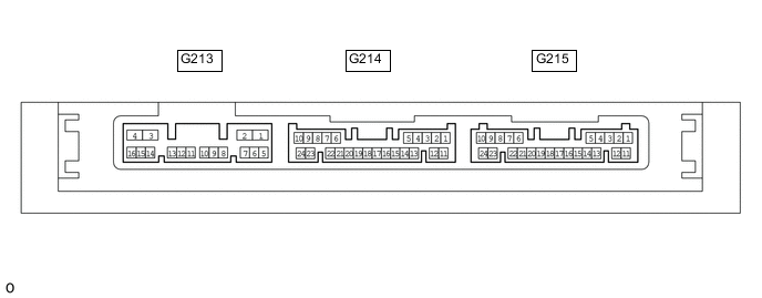
CHECK CERTIFICATION ECU (SMART KEY ECU ASSEMBLY) (w/ Entry and Start System)
-
Disconnect the G215 certification ECU (smart key ECU assembly) connector.
-
Measure the voltage and resistance according to the value(s) in the table below.
Terminal No. (Symbol) Wiring Color Terminal Description Condition Specified Condition G215-10 (+B) - Body ground V - Body ground Battery power supply Always 11 to 14 V G215-11 (E) - Body ground W-B - Body ground Ground Always Below 1 Ω -
Reconnect the G215 certification ECU (smart key ECU assembly) connector.
-
Measure the voltage according to the value(s) in the table below.
Terminal No. (Symbol) Wiring Color Terminal Description Condition Specified Condition G215-17 (SWIL) - G215-12 (AGND) B - GR Engine switch illumination operation signal Engine switch illumination on 11 to 14 V Engine switch illumination off Below 1 V
-
-
CHECK OUTER MIRROR CONTROL ECU ASSEMBLY LH (w/ Door Mirror Foot Light)

-
Disconnect the K12 outer mirror control ECU assembly LH connector.
-
Measure the voltage and resistance according to the value(s) in the table below.
Tester Connection Wiring Color Terminal Description Condition Specified Condition K12-5 (SIG) - K12-7 (GND) G - W-B Ignition power supply Ignition switch ON 11 to 14 V Ignition switch off Below 1 V K12-6 (CPUB) - K12-7 (GND) L - W-B Battery power supply Always 11 to 14 V K12-14 (BDR) - K12-7 (GND) R - W-B Battery power supply Always 11 to 14 V K12-7 (GND) - Body ground W-B - Body ground Ground Always Below 1 Ω -
Reconnect the K12 outer mirror control ECU assembly LH connector.
-
Measure the voltage according to the value(s) in the table below.
Tester Connection Wiring Color Terminal Description Condition Specified Condition z18-2 (LP+) - z18-12 (HTR-) - Outer rear view mirror assembly LH (foot light) output signal Outer rear view mirror assembly LH (foot light) on 11 to 14 V Outer rear view mirror assembly LH (foot light) off Below 1 V
-
-
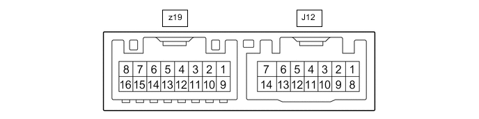
CHECK OUTER MIRROR CONTROL ECU ASSEMBLY RH (w/ Door Mirror Foot Light)
-
Disconnect the J12 outer mirror control ECU assembly RH connector.
-
Measure the voltage and resistance according to the value(s) in the table below.
Tester Connection Wiring Color Terminal Description Condition Specified Condition J12-5 (SIG) - J12-7 (GND) G - W-B Ignition power supply Ignition switch ON 11 to 14 V Ignition switch off Below 1 V J12-6 (CPUB) - J12-7 (GND) L - W-B Battery power supply Always 11 to 14 V J12-14 (BDR) - J12-7 (GND) G - W-B Battery power supply Always 11 to 14 V J12-7 (GND) - Body ground W-B - Body ground Ground Always Below 1 Ω -
Reconnect the J12 outer mirror control ECU assembly RH connector.
-
Measure the voltage according to the value(s) in the table below.
Tester Connection Wiring Color Terminal Description Condition Specified Condition z19-2 (LP+) - z19-12 (HTR-) - Outer rear view mirror assembly RH (foot light) output signal Outer rear view mirror assembly RH (foot light) on 11 to 14 V Outer rear view mirror assembly RH (foot light) off Below 1 V
-