THEFT DETERRENT SYSTEM(except 5L-E) Improper Operation
DESCRIPTION
When the theft deterrent system operates by itself, it could be due to something such as a short circuit in the courtesy light switch of any of the doors or the hood causing a signal to be sent in error.
Tech Tips
Preconditions for Arming Preparation:
-
The ignition switch is off and all the doors and the glass hatch*1 and the hood are closed and all doors are locked by wireless operation or entry operation*2.
-
*1: w/ Glass Hatch Opener System
-
*2: w/ Entry and Start System
WIRING DIAGRAM
CAUTION / NOTICE / HINT
Note
-
w/ Entry and Start System:
If the main body ECU (multiplex network body ECU) is replaced, refer to the Service Bulletin.
-
The theft deterrent system uses the CAN communication system. Inspect the communication function by following How to Proceed with Troubleshooting. Troubleshoot the theft deterrent system after confirming that the communication systems are functioning properly.
-
When using the GTS with the ignition switch off to troubleshoot:
Connect the GTS to the vehicle, and turn a courtesy light switch on and off at 1.5 second intervals until communication between the GTS and vehicle begins.
-
If the vehicle or vehicle controls are operated (for example, during initial inspection when the vehicle is brought in for repair) before operation history has been read out and saved, the operation history information could be lost.
-
The function "Read operation history" uses the current system time setting inside the GTS and the time counter inside the controlling ECU to calculate the timings shown in the operation history. For this reason, before reading out the operation history, first make sure that the GTS system clock is accurately set to the current time.
PROCEDURE
-
CUSTOMER PROBLEM ANALYSIS AND SYMPTOM CONFIRMATION
Tech Tips
-
In troubleshooting, confirm that the problem symptoms have been accurately identified. Preconceptions should be discarded in order to make an accurate judgment. To clearly understand what the problem symptoms are, it is extremely important to ask the customer about the problem and the conditions at the time the malfunction occurred.
-
Gather as much information as possible for reference. Past problems that seem unrelated may also help in some cases.
-
The following 5 items are important points in the problem analysis:
What? Vehicle model, system name When? Date, time, occurrence frequency, whether the problem occurred recently or has been occurring for a long time Where? Whether the problem occurs at a specific location Under what conditions? Whether the doors were locked or unlocked, whether the ignition switch was ON, whether the engine was starting How did it happen? Problem symptoms* -
*: Be sure to ask the customer in detail about the following points concerning the vehicle operating conditions, environment and problem, and then check for DTCs.
Result Proceed to NEXT
NEXT 
-
-
CHECK THEFT DETERRENT SYSTEM OPERATION HISTORY
-
Use the GTS to check the theft deterrent system operation history around the time that the malfunction reported by the customer occurred, based on the contents of the customer interview and the last recorded theft deterrent system operation history around the time that the problem is reported to have occurred.
-
On the GTS screen, enter the following menus: Body / Main Body / Utility / Operation History Analysis. According to the display on the GTS, read the operation history.
-
Check that there is theft deterrent system operation history as reported by the customer.
Tech Tips
Based on the displayed operation history, perform vehicle-side inspection, and perform repairs if a problem is found. If the vehicle has no malfunction, interview the customer about possible causes such as "the driver" and "environmental / other than the driver".
Result Result Proceed to There is operational history around the time that the customer reported the malfunction to have occurred, but the malfunction could not be identified even by following the instructions to inspect the relevant areas A There is operational history around the time that the customer reported the malfunction to have occurred, and by following the instructions to inspect the relevant areas, the malfunction was identified B There is no operational history around the time that the customer reported the malfunction to have occurred. C -
B 
INTERVIEW THE CUSTOMER Click here
C 
END
A
-
-
CHECK SECURITY INDICATOR LIGHT OPERATION
-
When the theft deterrent system is in arming preparation state, check that the security indicator light is illuminated.
-
When the theft deterrent system is in armed state, check that the security indicator light blinks.
Tech Tips
State of Theft Deterrent System Contents Security Indicator Light Condition Disarmed state (1), (2) Theft deterrent system is unset.
-
Off (Immobiliser function unset)
-
Blinking (Immobiliser function set)
Arming preparation state Standby period after theft deterrent system set conditions are met but before theft deterrent system is actually set (approximately 30 seconds).
(Theft detection not performed)
On Armed state Theft deterrent system is unset.
(Theft detection is possible)
Blinking (Immobiliser function set) Alarm sounding state Theft attempt is detected, and alarm is sounded using turn signal light, security horn assembly and vehicle horn.
(Alarm sounds for 27.5 seconds)
On Result Proceed to OK NG -
NG
GO TO OTHER PROBLEM Click here
OK
-
-
READ VALUE USING GTS (ACC SW, IG SW)
-
Connect the GTS to the DLC3.
-
Turn the ignition switch to ON.
-
Turn the GTS on.
-
Enter the following menus: Body Electrical / Main Body / Data List.
-
Read the Data List according to the display on the GTS.
Body Electrical > Main Body > Data List Tester Display Measurement Item Range Normal Condition Diagnostic Note ACC SW Ignition switch ON or OFF ON: ignition switch ACC or ON
OFF: ignition switch off
"ON" is also displayed for this item when the ignition switch is ON. IG SW Ignition switch ON or OFF ON: ignition switch ON
OFF: ignition switch off or ACC
"OFF" is also displayed for this item when the ignition switch is ACC. OK Normal conditions listed above are displayed. Result Proceed to OK NG
NG
GO TO LIGHTING SYSTEM Click here
OK
-
-
READ VALUE USING GTS (FR Door Lock Pos, FL Door Lock Pos, RR-Door Lock Pos SW, RL-Door Pos SW)
-
Connect the GTS to the DLC3.
-
Turn the ignition switch to ON.
-
Turn the GTS on.
-
Enter the following menus: Body Electrical / Main Body / Data List.
-
Read the Data List according to the display on the GTS.
Body Electrical > Main Body > Data List Tester Display Measurement Item Range Normal Condition Diagnostic Note FR Door Lock Pos Front door RH unlock detection switch LOCK or UNLOCK LOCK: Front door RH locked
UNLOCK: Front door RH unlocked
- FL Door Lock Pos Front door LH unlock detection switch LOCK or UNLOCK LOCK: Front door LH locked
UNLOCK: Front door LH unlocked
- RR-Door Lock Pos SW* Rear door RH unlock detection switch ON or OFF ON: Rear door RH unlocked
OFF: Rear door RH locked
- RL-Door Lock Pos SW* Rear door LH unlock detection switch ON or OFF ON: Rear door LH unlocked
OFF: Rear door LH locked
- Back Door Lock Pos SW Back door lock position switch status ON or OFF ON: Back door unlocked
OFF: Back door locked
-
-
*: for 5 Door
OK Normal conditions listed above are displayed. Result Proceed to OK NG -
NG
GO TO LIGHTING SYSTEM Click here
OK
-
-
READ VALUE USING GTS (FR Door Courtesy SW, FL Door Courtesy SW, RR Door Courtesy SW, RL Door Courtesy SW)
-
Connect the GTS to the DLC3.
-
Turn the ignition switch to ON.
-
Turn the GTS on.
-
Enter the following menus: Body Electrical / Main Body / Data List.
-
Read the Data List according to the display on the GTS.
Body Electrical > Main Body > Data List Tester Display Measurement Item Range Normal Condition Diagnostic Note FR Door Courtesy SW Front courtesy light switch RH ON or OFF ON: Front door RH open
OFF: Front door RH closed
- FL Door Courtesy SW Front courtesy light switch LH ON or OFF ON: Front door LH open
OFF: Front door LH closed
- RR Door Courtesy SW* Rear courtesy light switch RH ON or OFF ON: Rear door RH open
OFF: Rear door RH closed
- RL Door Courtesy SW* Rear courtesy light switch LH ON or OFF ON: Rear door LH open
OFF: Rear door LH closed
-
-
*: for 5 Door
OK Normal conditions listed above are displayed. Result Proceed to OK NG -
NG
GO TO LIGHTING SYSTEM Click here
OK
-
-
READ VALUE USING GTS (Back Door Courtesy SW)
-
Connect the GTS to the DLC3.
-
Turn the ignition switch to ON.
-
Turn the GTS on.
-
Enter the following menus: Body Electrical / Main Body / Data List.
-
Read the Data List according to the display on the GTS.
Body Electrical > Main Body > Data List Tester Display Measurement Item Range Normal Condition Diagnostic Note Back Door Courtesy SW Back door courtesy switch ON or OFF ON: Back door open
OFF: Back door closed
- OK Normal conditions listed above are displayed. Result Proceed to OK NG
NG
GO TO LIGHTING SYSTEM Click here
OK
-
-
READ VALUE USING GTS (Glass Hatch Courtesy SW) (w/ Glass Hatch Opener System)
-
Connect the GTS to the DLC3.
-
Turn the ignition switch to ON.
-
Turn the GTS on.
-
Enter the following menus: Body Electrical / Main Body / Data List.
-
Read the Data List according to the display on the GTS.
Body Electrical > Main Body > Data List Tester Display Measurement Item Range Normal Condition Diagnostic Note Glass Hatch Courtesy SW Glass hatch courtesy switch ON or OFF ON: Glass hatch open
OFF: Glass hatch closed
- OK Normal conditions listed above are displayed. Result Proceed to OK NG
NG
GO TO GLASS HATCH OPENER SYSTEM Click here
OK
-
-
READ VALUE USING GTS (Hood Courtesy SW)
-
Connect the GTS to the DLC3.
-
Turn the ignition switch to ON.
-
Turn the GTS on.
-
Enter the following menus: Body Electrical / Main Body / Data List.
-
Read the Data List according to the display on the GTS.
Body Electrical > Main Body > Data ListTester Display Measurement Item Range Normal Condition Diagnostic Note Hood Courtesy SW Engine hood courtesy switch ON or OFF ON: Engine hood open
OFF: Engine hood closed
- OK The GTS display changes correctly in response to the hood lock assembly (engine hood courtesy switch) status. Result Proceed to OK NG
NG
CHECK HARNESS AND CONNECTOR (HOOD LOCK ASSEMBLY [ENGINE HOOD COURTESY SWITCH] - MAIN BODY ECU [MULTIPLEX NETWORK BODY ECU] AND BODY GROUND) Click here
OK
-
-
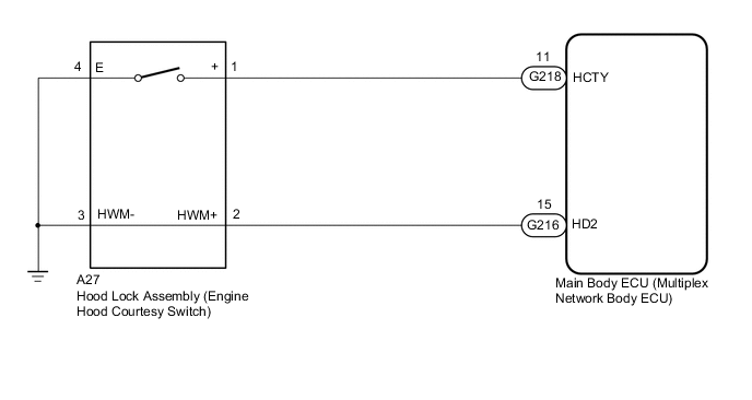
CHECK HARNESS AND CONNECTOR (HOOD LOCK ASSEMBLY [ENGINE HOOD COURTESY SWITCH] - MAIN BODY ECU [MULTIPLEX NETWORK BODY ECU] AND BODY GROUND)
-
Disconnect the A27 hood lock assembly (engine hood courtesy switch) connector.
-
Disconnect the G216 main body ECU (multiplex network body ECU) connector.
-
Measure the resistance according to the value(s) in the table below.
Standard Resistance Tester Connection Condition Specified Condition A27-2 (HWM+) - G216-15 (HD2) Always Below 1 Ω A27-3 (HWM-) - Body ground Always Below 1 Ω A27-2 (HWM+) or G216-15 (HD2) - Other terminals and body ground Always 10 kΩ or higher Result Proceed to OK NG
NG
REPAIR OR REPLACE HARNESS OR CONNECTOR
OK
-
-
INSPECT HOOD LOCK ASSEMBLY (ENGINE HOOD COURTESY SWITCH)
-
Remove the hood lock assembly (engine hood courtesy switch).
-
Inspect the hood lock assembly (engine hood courtesy switch).
Result Proceed to OK NG
OK
CHECK INTERMITTENT PROBLEMS Click here
NG
REPLACE HOOD LOCK ASSEMBLY (ENGINE HOOD COURTESY SWITCH) Click here
-
-
CHECK HARNESS AND CONNECTOR (HOOD LOCK ASSEMBLY [ENGINE HOOD COURTESY SWITCH] - MAIN BODY ECU [MULTIPLEX NETWORK BODY ECU] AND BODY GROUND)
-
Disconnect the A27 hood lock assembly (engine hood courtesy switch) connector.
-
Disconnect the G218 main body ECU (multiplex network body ECU) connector.
-
Measure the resistance according to the value(s) in the table below.
Standard Resistance Tester Connection Condition Specified Condition A27-1 (+) - G218-11 (HCTY) Always Below 1 Ω A27-4 (E) - Body ground Always Below 1 Ω A27-1 (+) or G218-11 (HCTY) - Other terminals and body ground Always 10 kΩ or higher Result Proceed to OK NG
NG
REPAIR OR REPLACE HARNESS OR CONNECTOR
OK
-
-
INSPECT HOOD LOCK ASSEMBLY (ENGINE HOOD COURTESY SWITCH)
-
Remove the hood lock assembly (engine hood courtesy switch).
-
Inspect the hood lock assembly (engine hood courtesy switch).
Result Proceed to OK NG
OK
REPLACE MAIN BODY ECU (MULTIPLEX NETWORK BODY ECU) Click here
NG
REPLACE HOOD LOCK ASSEMBLY (ENGINE HOOD COURTESY SWITCH) Click here
-
-
INTERVIEW THE CUSTOMER
-
If the phenomenon could not be confirmed or reproduced, after explaining this to the customer, also explain the history of input signals from the electrical key transmitter sub-assembly (electronic key) for the relevant date/time in the operation history.
Standard Cause was identified Result Proceed to OK NG
OK
END
NG
CHECK INTERMITTENT PROBLEMS Click here
-