THEFT DETERRENT SYSTEM(except 5L-E) Security Horn Circuit
DESCRIPTION
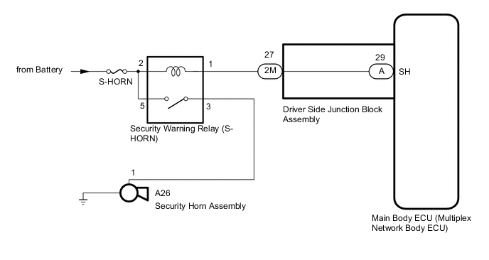
When the theft deterrent system is switched from the armed state to the alarm sounding state, the main body ECU (multiplex network body ECU) transmits a signal to cause the security horn to sound at intervals of 0.4 seconds.
WIRING DIAGRAM
CAUTION / NOTICE / HINT
Note
Inspect the fuses for circuits related to this system before performing the following procedure.
PROCEDURE
-
PERFORM ACTIVE TEST USING GTS (Security Horn)
-
Connect the GTS to the DLC3.
-
Turn the engine switch on (IG).
-
Turn the GTS on.
-
Enter the following menus: Body Electrical / Main Body / Active Test.
-
According to the display on the GTS, perform the Active Test.
Main Body Tester Display Measurement Item Control Range Diagnostic Note Security Horn Security horn assembly ON or OFF - OK The security horn assembly sounds and stops correctly when operated through the GTS. Result Proceed to OK NG
OK 
REPLACE MAIN BODY ECU (MULTIPLEX NETWORK BODY ECU) Click here
NG 
-
-
INSPECT SECURITY HORN ASSEMBLY
-
Remove the security horn assembly.
-
Inspect the security horn assembly.
Result Proceed to OK NG
NG
REPLACE SECURITY HORN ASSEMBLY Click here
OK
-
-
INSPECT SECURITY WARNING RELAY (S-HORN RELAY)
-
Remove the security warning relay (S-HORN relay).
-
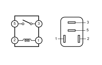
Measure the resistance according to the value(s) in the table below
Standard Resistance Tester Connection Condition Specified Condition 3 - 5 Battery voltage is applied between terminals 1 - 2 Below 1 Ω 3 - 5 Battery voltage is not applied between terminals 1 - 2 10 kΩ or higher Result Proceed to OK NG
NG
REPLACE SECURITY WARNING RELAY (S-HORN RELAY)
OK
-
-
CHECK HARNESS AND CONNECTOR (SECURITY WARNING RELAY (S-HORN RELAY) - MAIN BODY ECU (MULTIPLEX NETWORK BODY ECU))
-
Remove the main body ECU (multiplex network body ECU).
-
Connect the driver side junction block assembly connectors.
-
Remove the security warning relay (S-HORN relay).
-
Measure the resistance according to the value(s) in the table below.
Standard Resistance Tester Connection Condition Specified Condition 1 - A-29 (SH) Always Below 1 Ω 1 - Body ground Always 10 kΩ or higher A-29 (SH) - Body ground Always 10 kΩ or higher Result Proceed to OK NG
NG 
CHECK HARNESS AND CONNECTOR (SECURITY HORN RELAY - DRIVER SIDE JUNCTION BLOCK ASSEMBLY) Click here
OK
-
-
CHECK HARNESS AND CONNECTOR (BATTERY - SECURITY WARNING RELAY (S-HORN RELAY))
-
Remove the security warning relay (S-HORN relay).
-
Measure the voltage according to the value(s) in the table below.
Standard Voltage Tester Connection Condition Specified Condition 2 - Body ground Always 11 to 14 V 5 - Body ground Always 11 to 14 V Result Proceed to OK NG
NG
REPAIR OR REPLACE HARNESS OR CONNECTOR
OK
-
-
CHECK HARNESS AND CONNECTOR (SECURITY WARNING RELAY (S-HORN RELAY) - SECURITY HORN ASSEMBLY AND BODY GROUND)
-
Remove the security warning relay (S-HORN relay).
-
Disconnect the A26 security horn assembly connector.
-
Measure the resistance according to the value(s) in the table below.
Standard Resistance Tester Connection Condition Specified Condition 3 - A26-1 Always Below 1 Ω 3 - Body ground Always 10 kΩ or higher A26-1 - Body ground Always 10 kΩ or higher Result Proceed to OK NG
OK
REPLACE MAIN BODY ECU (MULTIPLEX NETWORK BODY ECU) Click here
NG
REPAIR OR REPLACE HARNESS OR CONNECTOR
-
-
CHECK HARNESS AND CONNECTOR (SECURITY HORN RELAY - DRIVER SIDE JUNCTION BLOCK ASSEMBLY)
-
Disconnect the 2M driver side junction block assembly connector.
-
Remove the security warning relay (S-HORN relay).
-
Measure the resistance according to the value(s) in the table below.
Standard Resistance Tester Connection Condition Specified Condition 1 - 2M-27 Always Below 1 Ω 1 - Body ground Always 10 kΩ or higher 2M-27 - Body ground Always 10 kΩ or higher Result Proceed to OK NG
OK
REPLACE DRIVER SIDE JUNCTION BLOCK ASSEMBLY Click here
NG
REPAIR OR REPLACE HARNESS OR CONNECTOR
-