LIGHTING SYSTEM TERMINALS OF ECU
-
CHECK DRIVER SIDE JUNCTION BLOCK ASSEMBLY, MAIN BODY ECU (MULTIPLEX NETWORK BODY ECU)
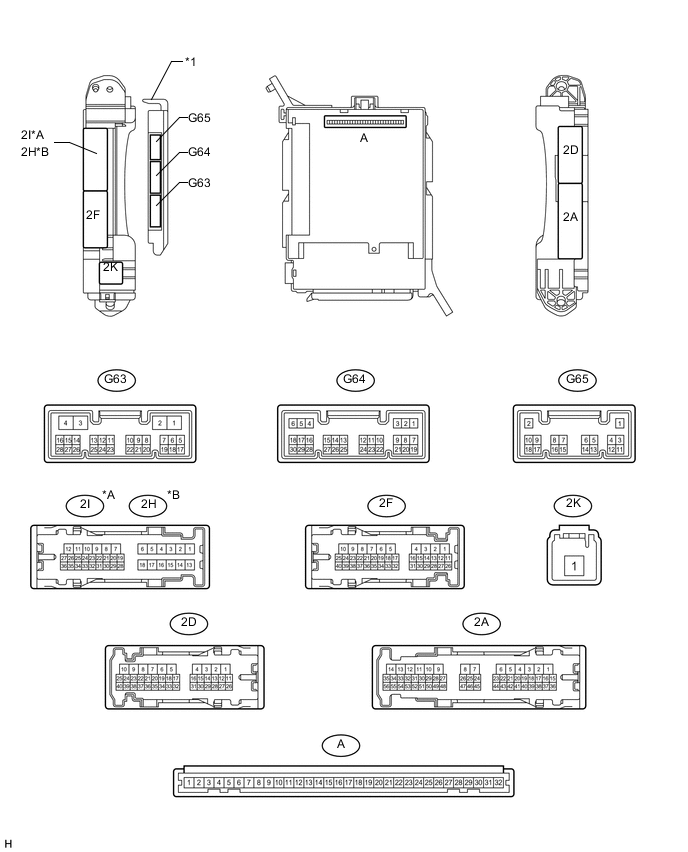
Text in Illustration *A for LHD *B for RHD *1 Main body ECU (multiplex network body ECU) - -
-
Remove the main body ECU Click here.
-
Measure the voltage and resistance according to the value(s) in the table below.
Terminal No. (Symbol) Wiring Color Terminal Description Condition Specified Condition A-29 (ACC) - Body ground - ACC power supply Ignition switch ACC 11 to 14 V A-30 (BECU) - Body ground - Battery power supply Always 11 to 14 V A-32 (IG) - Body ground - Ignition power supply Ignition switch ON 11 to 14 V A-11 (GND1) - Body ground - Ground Always Below 1 Ω G63-3 (GND2) - Body ground W-B - Body ground Ground Always Below 1 Ω If the result is not as specified, there may be a malfunction on the wire harness side.
-
Install the main body ECU Click here.
-
Measure the voltage according to the value(s) in the table below.
Terminal No. (Symbol) Wiring Color Terminal Description Condition Specified Condition G63-4 (OILE) - 2D-4 (GND1)*3 W - W-B Side step light signal output Side step light on 11 to 14 V Side step light off Below 1 V G63-5 (ILUP) - 2D-4 (GND1)*5 L - W-B Room light switch up signal Room light switch up Below 1 V Room light switch off 11 to 14 V 2D-13 (ILDN) - 2D-4 (GND1)*5 B - W-B Room light switch down signal Room light switch down Below 1 V Room light switch off 11 to 14 V G64-1 (GCTY) - 2D-4 (GND1)*6 V - W-B Glass hatch courtesy light switch signal Glass hatch open Below 1 V Glass hatch closed Pulse generation
(See waveform 1 or 2)
G64-2 (DOMR) - 2D-4 (GND1) GR - W-B Battery saving control (interior light auto cut function) signal Battery saving control (interior light auto cut function) not operating Below 1 V Battery saving control (interior light auto cut function) operating 11 to 14 V G64-6 (RCTY) - 2D-4 (GND1) R - W-B Rear door courtesy light switch RH signal Rear door RH open Below 1 V Rear door RH closed 11 to 14 V G64-19 (BCTY) - 2D-4 (GND1) G - W-B Back door courtesy light switch signal Back door open Below 1 V Back door closed Pulse generation
(See waveform 3 or 4)
G65-2 (OSPT) - 2D-4 (GND1)*5 SB - W-B Front door illumination signal Front door illumination on Below 1 V Front door illumination off 11 to 14 V G65-3 (LCTY) - 2D-4 (GND1) V - W-B Rear door courtesy light switch LH signal Rear door LH open Below 1 V Rear door LH closed 11 to 14 V G65-5 (CSPT) - 2D-4 (GND1) GR - W-B Center console spot light signal Ignition switch off 11 to 14 V Ignition switch ON or ACC Below 1 V G65-6 (TSPT) - 2D-4 (GND1)*5 SB - W-B Rear door illumination signal Rear door illumination on Below 1 V Rear door illumination off 11 to 14 V 2D-15 (FRCY) - 2D-4 (GND1)*1
2H-26 (FRCY) - 2D-4 (GND1)*2
B - W-B Front door courtesy light switch RH signal Front door RH open Below 1 V Front door RH closed 11 to 14 V 2D-18 (ILE) - 2D-4 (GND1) G - W-B Interior light signal Interior light on Below 1 V Interior light off 11 to 14 V 2D-36 (FSPT) - 2D-4 (GND1)*4 SB - W-B Interior foot light signal Interior foot light on Below 1 V Interior foot light off 11 to 14 V 2I-27 (FLCY) - 2D-4 (GND1)*1
2D-31 (FLCY) - 2D-4 (GND1)*2
R - W-B Front door courtesy light switch LH signal Front door LH open Below 1 V Front door LH closed 11 to 14 V
-
*1: for LHD
-
*2: for RHD
-
*3: w/ Side Step Light
-
*4: w/ Interior Foot Light
-
*5: w/ Door Illumination
-
*6: w/ Glass Hatch Opener System
If the result is not as specified, the main body ECU may have a malfunction.
-
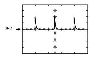
Waveform 1
Item Content Terminal No. (Symbol) G64-1 (GCTY) - 2D-4 (GND1) Tool setting 5 V/DIV., 20 ms./DIV. Condition Glass hatch closed -
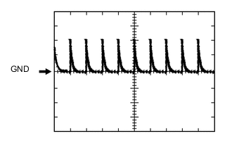
Waveform 2
Item Content Terminal No. (Symbol) G64-1 (GCTY) - 2D-4 (GND1) Tool setting 5 V/DIV., 20 ms./DIV. Condition Glass hatch closed -
Waveform 3
Item Content Terminal No. (Symbol) G64-19 (BCTY) - 2D-4 (GND1) Tool setting 5 V/DIV., 20 ms./DIV. Condition Back door closed -
Waveform 4
Item Content Terminal No. (Symbol) G64-19 (BCTY) - 2D-4 (GND1) Tool setting 5 V/DIV., 20 ms./DIV. Condition Back door closed
-
-