THEFT DETERRENT SYSTEM(for 5L-E) Horn Circuit
DESCRIPTION
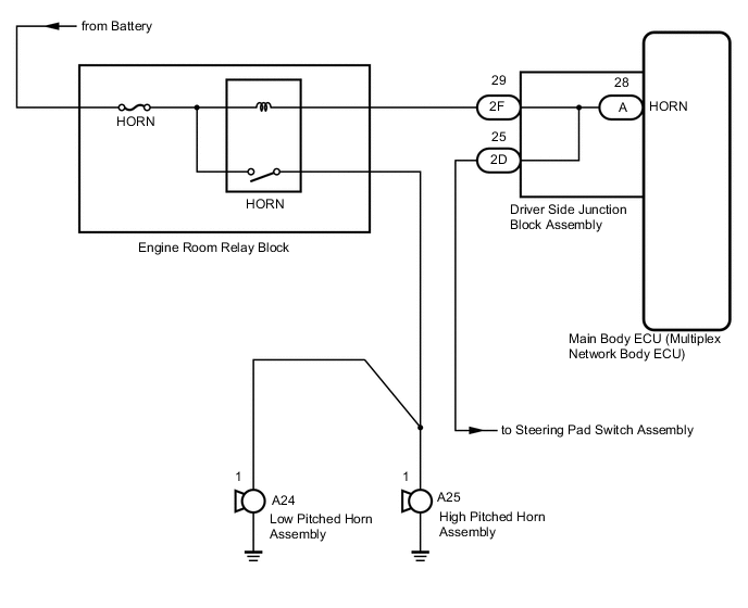
When the theft deterrent system is switched from the armed state to the alarm sounding state, the main body ECU (multiplex network body ECU) transmits a signal to cause the horn to sound at intervals of 0.4 seconds.
WIRING DIAGRAM
CAUTION / NOTICE / HINT
Note
Inspect the fuses for circuits related to this system before performing the following procedure.
PROCEDURE
-
CHECK HORNS OPERATION
-
Press the horn switch and check if the horns sound.
Result Result Proceed to Horns sound A Horns do not sound B
B 
GO TO HORN SYSTEM Click here
A 
-
-
INSPECT DRIVER SIDE JUNCTION BLOCK ASSEMBLY
-
Remove the driver side junction block assembly.
-
Measure the resistance according to the value(s) in the table below.
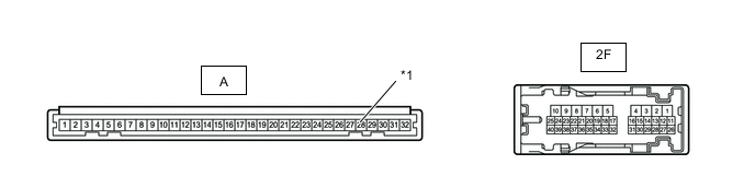
*1 HORN Standard Resistance Tester Connection Condition Specified Condition 2F-29 - A-28 (HORN) Always Below 1 Ω
OK
REPLACE MAIN BODY ECU (MULTIPLEX NETWORK BODY ECU) Click here
NG
REPLACE DRIVER SIDE JUNCTION BLOCK ASSEMBLY Click here
-