THEFT DETERRENT SYSTEM Horn Circuit
DESCRIPTION
When the theft deterrent system is in the alarm sounding state, the main body ECU outputs a signal repeatedly at 0.4 second intervals, causing the horns to sound.
WIRING DIAGRAM
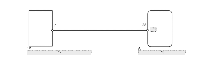
| *1 | HORN |
| *2 | No. 1 Integration Relay (Horn Relay) |
| *3 | Main Body ECU (Multiplex Network Body ECU) |
PROCEDURE
-
CHECK HORN OPERATION
-
Press the horn switch and check if the horns sound.
OK Horns operate normally.
NG 
GO TO HORN SYSTEM Click here
OK 
-
-
PERFORM ACTIVE TEST USING INTELLIGENT TESTER (VEHICLE HORN)
-
Operate the intelligent tester according to the steps on the display and select Active Test Click here.
Main Body Tester Display Test Part Control Range Diagnostic Note Vehicle Horn Vehicle horns ON/OFF - OK Horns operate normally.
OK
PROCEED TO NEXT SUSPECTED AREA SHOWN IN PROBLEM SYMPTOMS TABLE Click here
NG
-
-
CHECK HARNESS AND CONNECTOR (NO. 1 INTEGRATION RELAY - MAIN BODY ECU)
-
Disconnect the 1A relay connector.
-
Remove the main body ECU Click here.
-
Measure the resistance according to the value(s) in the table below.
Standard Resistance Tester Connection Condition Specified Condition 1A-7 - A-28 (HORN) Always Below 1 Ω 1A-7 or A-28 (HORN) - Body ground Always 10 kΩ or higher
OK
REPLACE MAIN BODY ECU (MULTIPLEX NETWORK BODY ECU) Click here
NG
REPAIR OR REPLACE HARNESS OR CONNECTOR
-