THEFT DETERRENT SYSTEM(except 5L-E), Diagnostic DTC:B2762
| DTC Code | DTC Name |
|---|---|
| B2762 | Intrusion Sensor Signal Circuit Malfunction |
DESCRIPTION
The intrusion and tilt sensor (theft warning ultrasonic sensor) conducts self-diagnosis immediately after power is supplied to the sensor (when the theft deterrent system is set).
If a malfunction is detected in the ISIF line, the main body ECU (multiplex network body ECU) stores this DTC.
| DTC Code | Detection Item | DTC Detection Condition | Trouble Area |
|---|---|---|---|
| B2762 | Intrusion Sensor Signal Circuit Malfunction |
After normal/trouble signal is output from intrusion and tilt sensor (theft warning ultrasonic sensor) as result of self-diagnosis, following malfunctions are detected: |
|
WIRING DIAGRAM
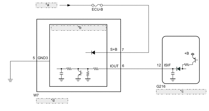
| *a | from Battery |
| *b | Intrusion and Tilt Sensor (Theft Warning Ultrasonic Sensor) |
| *c | Main Body ECU (Multiplex Network Body ECU) |
| *d | Map Light Assembly |
CAUTION / NOTICE / HINT
Note
-
Inspect the fuses for circuits related to this system before performing the following procedure.
-
w/ Entry and Start System:
If the main body ECU (multiplex network body ECU) is replaced, refer to the Service Bulletin.
PROCEDURE
-
CHECK HARNESS AND CONNECTOR (MAP LIGHT ASSEMBLY - BATTERY AND BODY GROUND)
-
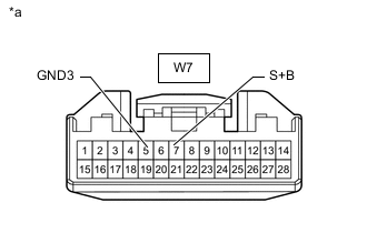
*a Front view of wire harness connector
(to Map Light Assembly)
Disconnect the map light assembly connectors.
-
Measure the voltage according to the value(s) in the table below.
Standard Voltage Tester Connection Switch Condition Specified Condition W7-7 (S+B) - Body ground Always 11 to 14 V -
Measure the resistance according to the value(s) in the table below.
Standard Resistance Tester Connection Condition Specified Condition W7-5 (GND3) - Body ground Always Below 1 Ω Result Proceed to OK NG
NG 
REPAIR OR REPLACE HARNESS OR CONNECTOR
OK 
-
-
CHECK WAVEFORM (INTRUSION AND TILT SENSOR [THEFT WARNING ULTRASONIC SENSOR]) (IOUT)
-
Using an oscilloscope, check the waveform.
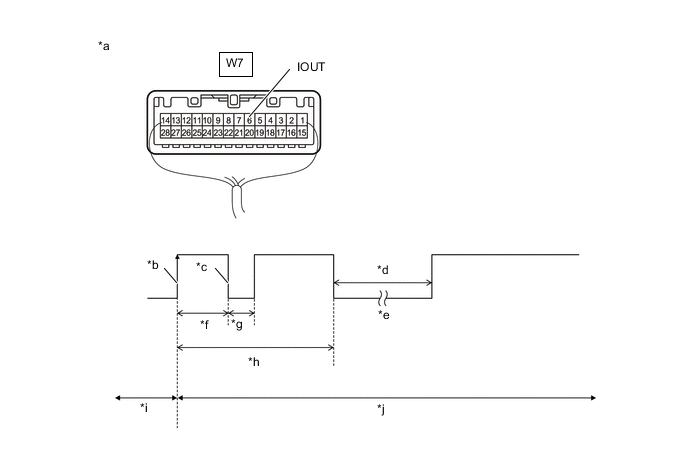
*a Component with harness connected
(Map Light Assembly)
*b IOUT Initial Signal *c IOUT Initial Response *d Approximately 1.0 second *e Initial Diagnosis *f Approximately 1.0 to 1.6 seconds *g Approximately 0.05 seconds *h Approximately 5.5 seconds *i Disarmed State *j Arming Preparation State Measurement Condition Tester Connection Content Tester Connection W7-6 (IOUT) - Body ground Tool Setting 2 V/DIV., 100 ms./DIV. Condition Theft deterrent system is set (system changes from disarmed state to arming preparation state) Tech Tips
-
If the intrusion and tilt sensor (theft warning ultrasonic sensor) is normal, an initial response is output in response to the HI input from the main body ECU (multiplex network body ECU).
-
If the waveform output remains LO, there may be a problem with the main body ECU (multiplex network body ECU), as there is no input from the main body ECU (multiplex network body ECU).
OK The waveform displays properly (HI is 6.5 V or higher and LO is below 1 V). Result Result Proceed to OK (There is an initial response) A NG (Waveform output remains LO) B NG (There is no initial response and the waveform output remains HI) C -
A
USE SIMULATION METHOD TO CHECK Click here
C 
INSPECT MAP LIGHT ASSEMBLY Click here
B
-
-
CHECK HARNESS AND CONNECTOR (MAIN BODY ECU [MULTIPLEX NETWORK BODY ECU] - MAP LIGHT ASSEMBLY)
-
Disconnect the G216 main body ECU (multiplex network body ECU) connector.
-
Disconnect the W7 map light assembly connector.
-
Measure the resistance according to the value(s) in the table below.
Standard Resistance Tester Connection Condition Specified Condition G216-12 (ISIF) - W7-6 (IOUT) Always Below 1 Ω G216-12 (ISIF) or W7-6 (IOUT) - Other terminals and body ground Always 10 kΩ or higher Result Proceed to OK NG
OK
REPLACE MAIN BODY ECU (MULTIPLEX NETWORK BODY ECU) Click here
NG
REPAIR OR REPLACE HARNESS OR CONNECTOR
-
-
INSPECT MAP LIGHT ASSEMBLY
-
Remove the map light assembly.
-
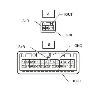
Measure the resistance according to the value(s) in the table below.
Standard Resistance Tester Connection Condition Specified Condition A-1 (GND) - B-5 (GND) Always Below 1 Ω A-2 (IOUT) - B-6 (IOUT) Always Below 1 Ω A-4 (S+B) - B-7 (S+B) Always Below 1 Ω Result Proceed to OK NG
OK
REPLACE INTRUSION AND TILT SENSOR (THEFT WARNING ULTRASONIC SENSOR) Click here
NG
REPLACE MAP LIGHT ASSEMBLY Click here
-