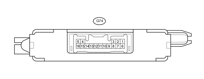
ENGINE IMMOBILISER SYSTEM(w/o Entry and Start System) TERMINALS OF ECU
-
CHECK TRANSPONDER KEY ECU ASSEMBLY
-
Disconnect the G74 transponder key ECU assembly connector.
-
Measure the voltage and resistance according to the value(s) in the table below.
Tech Tips
Measure the values on the wire harness side with the connector disconnected.
Tester Connection Input/Output Wiring Color Terminal Description Condition Specified Condition Related Data List Item G74-1 (+B) - G74-5 (GND) Input P - W-B Battery Always 11 to 14 V +B G74-2 (IG) - G74-5 (GND) Input W - W-B Ignition switch signal Ignition switch off Below 1 V IG SW Ignition switch ON 11 to 14 V G74-3 (KSW) - G74-5 (GND) Input G - W-B Unlock warning switch signal No key in ignition key cylinder 10 kΩ or higher Key SW/B2780 Key in ignition key cylinder Below 1 Ω G74-5 (GND) - Body ground - W-B - Body ground Ground Always Below 1 Ω - G74-7 (CTY) - Body ground Input R - Body ground*1
B - Body ground*2
Door courtesy switch (for driver side) signal Driver side door closed 10 kΩ or higher - Driver side door open Below 1 Ω
-
*1: for LHD
-
*2: for RHD
-
-
Reconnect the G74 transponder key ECU assembly connector.
-
Measure the voltage and check for pulses according to the value(s) in the table below.
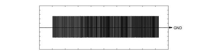
Tester Connection Input/Output Wiring Color Terminal Description Condition Specified Condition Related Data List Item G74-8 (IND) - G74-5 (GND) Output G - W-B Security indicator signal No key in ignition key cylinder, or 20 sec. elapsed after turning ignition switch to ACC or off (immobiliser system set) Pulse generation Immobiliser Key in ignition key cylinder (immobiliser system unset) Below 1 V G74-9 (D) - G74-5 (GND) Input/Output W - W-B DLC3 communication Without communication Below 1 V - During communication Pulse generation G74-4 (ANT1) - G74-5 (GND) Input/Output R - W-B Transponder key amplifier power source No key in ignition key cylinder 4 to 6 V - Within 3 seconds of inserting key into ignition key cylinder Pulse generation
(See waveform 1)
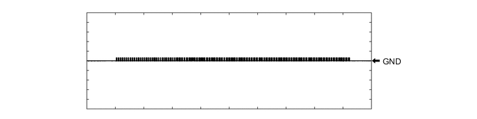
G74-15 (ANT2) - G74-5 (GND) Input/Output G - W-B Transponder key amplifier communication signal No key in ignition key cylinder 4 to 6 V - Within 3 seconds of inserting key into ignition key cylinder Pulse generation
(See waveform 2)
G74-12 (EFII) - G74-5 (GND) Output SB - W-B ECM input signal Ignition switch off 11 to 14 V - Within 3 seconds of starter operation and initial combustion, or within 3 seconds of ignition switch first being turned to ON after cable disconnected and reconnected to negative (-) battery terminal Pulse generation
(See waveform 3)
- G74-13 (EFIO) - G74-5 (GND) Input W - W-B ECM output signal Ignition switch off Below 1 V - Within 3 seconds of starter operation and initial combustion, or within 3 seconds of ignition switch first being turned to ON after cable disconnected and reconnected to negative (-) battery terminal Pulse generation
(See waveform 4)
-
Using an oscilloscope, check the waveform.
-
Waveform 1 (Reference)
Tester Connection G74-4 (ANT1) - G74-5 (GND) Tool Setting 2 V/DIV., 500 ms./DIV. Condition Within 3 seconds of inserting key into ignition key cylinder -
Waveform 2 (Reference)
Tester Connection G74-15 (ANT2) - G74-5 (GND) Tool Setting 2 V/DIV., 500 ms./DIV. Condition Within 3 seconds of inserting key into ignition key cylinder -
Waveform 3 (Reference)
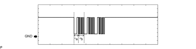
Text in Illustration *a Approximately 160 ms *b Approximately 270 ms Tester Connection G74-12 (EFII) - G74-5 (GND) Tool Setting 2 V/DIV., 500 ms./DIV. Condition Within 3 seconds of starter operation and initial combustion, or within 3 seconds of ignition switch first being turned to ON after cable disconnected and reconnected to negative (-) battery terminal -
Waveform 4 (Reference)
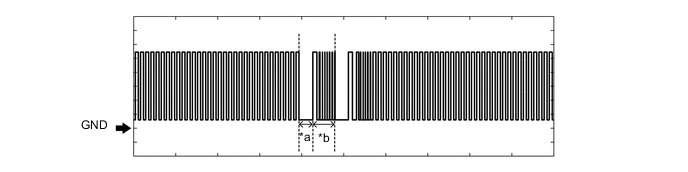
Text in Illustration *a Approximately 160 ms *b Approximately 270 ms Tester Connection G74-13 (EFIO) - G74-5 (GND) Tool Setting 2 V/DIV., 500 ms./DIV. Condition Ignition switch ON
-
-
-
CHECK ECM (for 1KD-FTV)
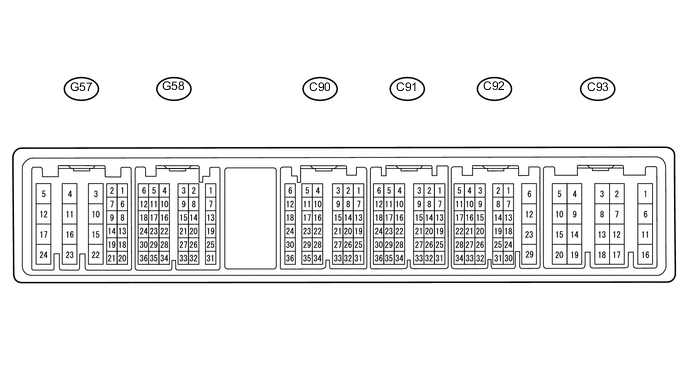
Tester Connection Input/Output Wiring Color Terminal Description Condition Specified Condition Related Data List Item C93-1 (E1) - Body ground - BR - Body ground Ground Always Below 1 Ω - C93-12 (E01) - Body ground - W-B - Body ground Ground Always Below 1 Ω - C93-13 (E02) - Body ground - W-B - Body ground Ground Always Below 1 Ω - G57-23 (BATT) - C93-1 (E1) Input L - BR +B power supply Always 11 to 14 V - G57-24 (+B) - C93-1 (E1) Input W - BR IG power supply Ignition switch ON 11 to 14 V - G57-17 (+B2) - C93-1 (E1) Input W - BR IG power supply Ignition switch ON 11 to 14 V - G58-29 (IMO) - C93-1 (E1) Input SB - BR Transponder key ECU assembly communication input Ignition switch off 11 to 14 V - Within 3 seconds of starter operation and initial combustion, or within 3 seconds of ignition switch first being turned to ON after cable disconnected and reconnected to negative (-) battery terminal Pulse generation
(See waveform 1)
- G58-28 (IMI) - C93-1 (E1) Output W - BR Transponder key ECU assembly communication output Ignition switch off Below 1 V - Within 3 seconds of starter operation and initial combustion, or within 3 seconds of ignition switch first being turned to ON after cable disconnected and reconnected to negative (-) battery terminal Pulse generation
(See waveform 2)
-
-
Using an oscilloscope, check the waveform.
-
Waveform 1 (Reference)
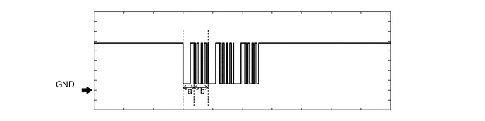
Text in Illustration *a Approximately 160 ms *b Approximately 270 ms Tester Connection G58-29 (IMO) - C93-1 (E1) Tool Setting 2 V/DIV., 500 ms./DIV. Condition Within 3 seconds of starter operation and initial combustion, or within 3 seconds of ignition switch first being turned to ON after cable disconnected and reconnected to negative (-) battery terminal -
Waveform 2 (Reference)
Text in Illustration *a Approximately 160 ms *b Approximately 270 ms Tester Connection G58-28 (IMI) - C93-1 (E1) Tool Setting 2 V/DIV., 500 ms./DIV. Condition Ignition switch ON
-
-
-
CHECK ECM (for 2TR-FE)
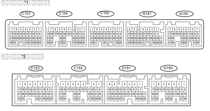
*1 for Automatic Transmission: *2 for Manual Transmission: Tester Connection Input/Output Wiring Color Terminal Description Condition Specified Condition Related Data List Item C153-3 (E1) - Body ground - BR - Body ground Ground Always Below 1 Ω - C153-1 (E01) - Body ground - W-B - Body ground Ground Always Below 1 Ω - C153-2 (E02) - Body ground - W-B - Body ground Ground Always Below 1 Ω - G180-3 (BATT) - C153-3 (E1) Input L - BR +B power supply Always 11 to 14 V - G180-1 (+B) - C153-3 (E1) Input W - BR IG power supply Ignition switch ON 11 to 14 V - G180-2 (+B2) - C153-3 (E1) Input W - BR IG power supply Ignition switch ON 11 to 14 V - G181-9 (IMO) - C153-3 (E1) Input SB - BR Transponder key ECU assembly communication input Ignition switch off 11 to 14 V - Within 3 seconds of starter operation and initial combustion, or within 3 seconds of ignition switch first being turned to ON after cable disconnected and reconnected to negative (-) battery terminal Pulse generation
(See waveform 1)
- G181-10 (IMI) - C153-3 (E1) Output W - BR Transponder key ECU assembly communication output Ignition switch off Below 1 V - Within 3 seconds of starter operation and initial combustion, or within 3 seconds of ignition switch first being turned to ON after cable disconnected and reconnected to negative (-) battery terminal Pulse generation
(See waveform 2)
-
-
Using an oscilloscope, check the waveform.
-
Waveform 1 (Reference)
Text in Illustration *a Approximately 160 ms *b Approximately 270 ms Tester Connection G181-9 (IMO) - C153-3 (E1) Tool Setting 2 V/DIV., 500 ms./DIV. Condition Within 3 seconds of starter operation and initial combustion, or within 3 seconds of ignition switch first being turned to ON after cable disconnected and reconnected to negative (-) battery terminal -
Waveform 2 (Reference)
Text in Illustration *a Approximately 160 ms *b Approximately 270 ms Tester Connection G181-10 (IMI) - C153-3 (E1) Tool Setting 2 V/DIV., 500 ms./DIV. Condition Ignition switch ON
-
-
-
CHECK ECM (for 5L-E)
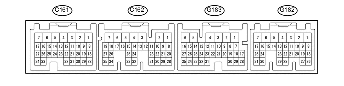
Tester Connection Input/Output Wiring Color Terminal Description Condition Specified Condition Related Data List Item C161-5 (E1) - Body ground - BR - Body ground Ground Always Below 1 Ω - C161-7 (E01) - Body ground - W-B - Body ground Ground Always Below 1 Ω - C161-6 (E02) - Body ground - W-B - Body ground Ground Always Below 1 Ω - G183-2 (BATT) - C161-5 (E1) Input L - BR +B power supply Always 11 to 14 V - G183-1 (+B) - C161-5 (E1) Input W - BR IG power supply Ignition switch ON 11 to 14 V - G182-18 (IMO) - C161-5 (E1) Input SB - BR Transponder key ECU assembly communication input Ignition switch off 11 to 14 V - Within 3 seconds of starter operation and initial combustion, or within 3 seconds of ignition switch first being turned to ON after cable disconnected and reconnected to negative (-) battery terminal Pulse generation
(See waveform 1)
- G182-19 (IMI) - C161-5 (E1) Output W - BR Transponder key ECU assembly communication output Ignition switch off Below 1 V - Within 3 seconds of starter operation and initial combustion, or within 3 seconds of ignition switch first being turned to ON after cable disconnected and reconnected to negative (-) battery terminal Pulse generation
(See waveform 2)
-
-
Using an oscilloscope, check the waveform.
-
Waveform 1 (Reference)
Text in Illustration *a Approximately 160 ms *b Approximately 270 ms Tester Connection G182-18 (IMO) - C161-5 (E1) Tool Setting 2 V/DIV., 500 ms./DIV. Condition Within 3 seconds of starter operation and initial combustion, or within 3 seconds of ignition switch first being turned to ON after cable disconnected and reconnected to negative (-) battery terminal -
Waveform 2 (Reference)
Text in Illustration *a Approximately 160 ms *b Approximately 270 ms Tester Connection G182-19 (IMI) - C161-5 (E1) Tool Setting 2 V/DIV., 500 ms./DIV. Condition Ignition switch ON
-
-