ENGINE IMMOBILISER SYSTEM(w/ Entry and Start System) ID Code Box Power Source Circuit
DESCRIPTION
This circuit provides power to operate the ID code box.
WIRING DIAGRAM
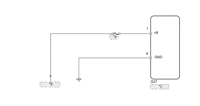
| *a | SMART |
| *b | from Battery |
| *c | ID Code Box |
CAUTION / NOTICE / HINT
Note
Inspect the fuses for circuits related to this system before performing the following inspection procedure.
PROCEDURE
-
CHECK HARNESS AND CONNECTOR (ID CODE BOX - BATTERY AND BODY GROUND)
-
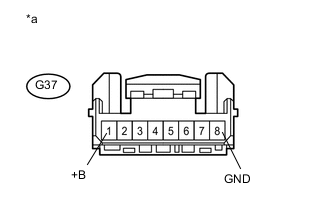
Text in Illustration *a Front view of wire harness connector
(to ID Code Box)
Disconnect the G37 box connector.
-
Measure the voltage according to the value(s) in the table below.
Standard Voltage Tester Connection Condition Specified Condition G37-1 (+B) - Body ground Always 11 to 14 V -
Measure the resistance according to the value(s) in the table below.
Standard Resistance Tester Connection Condition Specified Condition G37-8 (GND) - Body ground Always Below 1 Ω
OK 
PROCEED TO NEXT SUSPECTED AREA SHOWN IN PROBLEM SYMPTOMS TABLE Click here
NG
REPAIR OR REPLACE HARNESS OR CONNECTOR
-