ENGINE IMMOBILISER SYSTEM(w/ Entry and Start System) TERMINALS OF ECU
-
CHECK ENGINE SWITCH

-
Disconnect the G36 switch connector.
-
Measure the resistance according to the value(s) in the table below.
Terminal No. (Symbol) Wiring Color Terminal Description Condition Specified Condition G36-8 (AGND) - Body ground GR - Body ground Ground Always Below 1 Ω G36-5 (GND) - Body ground W-B - Body ground Ground Always Below 1 Ω -
Reconnect the G36 switch connector.
-
Measure the voltage according to the value(s) in the table below.
Terminal No. (Symbol) Wiring Color Terminal Description Condition Specified Condition G36-9 (TXCT) - G36-8 (AGND) W - GR Key code output signal Engine switch off, 30 seconds or more after door opened or closed and brake pedal*1 or clutch pedal*2 not depressed Below 1 V G36-9 (TXCT) - G36-8 (AGND) W - GR Key code output signal Engine switch off, key not in cabin and 30 seconds or less after engine switch pushed Pulse generation
(see waveform 1)
G36-10 (CODE) - G36-8 (AGND) V - GR Demodulated signal of key code data Engine switch off, 30 seconds or more after door opened or closed and brake pedal*1 or clutch pedal*2 not depressed Below 1 V G36-10 (CODE) - G36-8 (AGND) V - GR Demodulated signal of key code data Engine switch off, key held against engine switch and engine switch pushed*3 Pulse generation
(see waveform 2)
G36-11 (SWIL) - G36-5 (GND) B - W-B Illumination signal Light control switch off → tail Below 2 V → 9 to 14 V G36-14 (VC5) - G36-8 (AGND) P - GR Power supply Engine switch off, 30 seconds or more after door opened or closed and brake pedal*1 or clutch pedal*2 not depressed Below 1 V G36-14 (VC5) - G36-8 (AGND) P - GR Power supply Engine switch off, key not in cabin and 30 seconds or less after engine switch pushed Pulse generation
(see waveform 3)
-
*1: for Automatic Transmission
-
*2: for Manual Transmission
Tech Tips
*3: Remove the key battery before performing this inspection.
-
-
Inspect using an oscilloscope.
-

Waveform 1 (Reference)
Measurement Condition Item Content Tester Connection G36-9 (TXCT) - G36-8 (AGND) Tool Setting 2 V/DIV., 20 ms./DIV. Condition Engine switch off, key not in cabin and 30 seconds or less after engine switch pushed -
Waveform 2 (Reference)
Measurement Condition Item Content Tester Connection G36-10 (CODE) - G36-8 (AGND) Tool Setting 2 V/DIV., 20 ms./DIV. Condition Engine switch off, key held against engine switch and engine switch pushed* Tech Tips
*: Remove the key battery before performing this inspection.
-
Waveform 3 (Reference)
Measurement Condition Item Content Tester Connection G36-14 (VC5) - G36-8 (AGND) Tool Setting 2 V/DIV., 20 ms./DIV. Condition Engine switch off, key not in cabin and 30 seconds or less after engine switch pushed
-
-
-
CHECK CERTIFICATION ECU
-
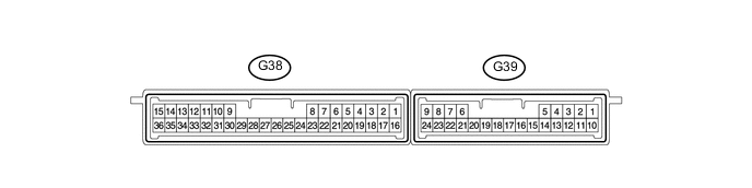
Disconnect the G38 ECU connector.
-
Measure the resistance and voltage according to the value(s) in the table below.
Terminal No. (Symbol) Wiring Color Terminal Description Condition Specified Condition G38-1 (+B) - G38-15 (E) V - W-B +B power supply Always 11 to 14 V G38-17 (CUTB) - G38-15 (E) L - W-B +B power supply Always 11 to 14 V G38-16 (IG) - G38-15 (E) W - W-B Ignition power supply Engine switch off → on (IG) Below 1 V → 11 to 14 V G38-15 (E) - Body ground W-B - Body ground Ground Always Below 1 Ω -
Reconnect the G38 ECU connector.
-
Measure the resistance and voltage according to the value(s) in the table below.
Terminal No. (Symbol) Wiring Color Terminal Description Condition Specified Condition G38-2 (IND) - G38-15 (E) G - W-B Security indicator output Engine switch off → on (IG) Pulse generation
→ Below 2 V
G38-11 (SWIL) - G38-36 (AGND) B - GR Illumination signal Light control switch off Below 2 V G38-11 (SWIL) - G38-36 (AGND) B - GR Illumination signal Light control switch tail 9 to 14 V G38-12 (TXCT) - G38-36 (AGND) W - GR Engine switch TXCT output Engine switch off, 30 seconds or more after door opened or closed and brake pedal*1 or clutch pedal*2 not depressed Below 1 V G38-12 (TXCT) - G38-36 (AGND) W - GR Engine switch TXCT output Engine switch off, key not in cabin and 30 seconds or less after engine switch pushed Pulse generation
(see waveform 1)
G38-13 (CODE) - G38-36 (AGND) V - GR Engine switch CODE input Key not in cabin Below 1 V G38-13 (CODE) - G38-36 (AGND) V - GR Engine switch CODE input Engine switch off, key held against engine switch and engine switch pushed*3 Pulse generation
(see waveform 2)
G38-28 (VC5) - G38-36 (AGND) P - GR Engine switch power supply Engine switch off, 30 seconds or more after door opened or closed and brake pedal*1 or clutch pedal*2 not depressed Below 1 V G38-28 (VC5) - G38-36 (AGND) P - GR Engine switch power supply Engine switch off, key not in cabin and 30 seconds or less after engine switch pushed Pulse generation
(see waveform 3)
G38-36 (AGND) - Body ground GR - Body ground Engine switch ground Always Below 1 Ω
-
*1: for Automatic Transmission
-
*2: for Manual Transmission
Tech Tips
*3: Remove the key battery before performing this inspection.
-
-
Inspect using an oscilloscope.
-
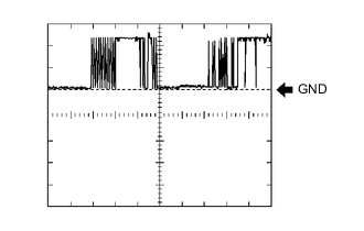
Waveform 1 (Reference)
Measurement Condition Item Content Tester Connection G38-12 (TXCT) - G38-36 (AGND) Tool Setting 2 V/DIV., 20 ms./DIV. Condition Engine switch off, key not in cabin and 30 seconds or less after engine switch pushed -

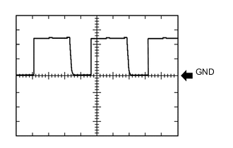
Waveform 2 (Reference)
Measurement Condition Item Content Tester Connection G38-13 (CODE) - G38-36 (AGND) Tool Setting 2 V/DIV., 20 ms./DIV. Condition Engine switch off, key held against engine switch and engine switch pushed* Tech Tips
*: Remove the key battery before performing this inspection.
-
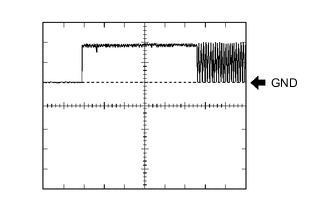
Waveform 3 (Reference)
Measurement Condition Item Content Tester Connection G38-28 (VC5) - G38-36 (AGND) Tool Setting 2 V/DIV., 20 ms./DIV. Condition Engine switch off, key not in cabin and 30 seconds or less after engine switch pushed
-
-
-
CHECK ID CODE BOX

-
Disconnect the G37 box connector.
-
Measure the resistance and voltage according to the value(s) in the table below.
Terminal No. (Symbol) Wiring Color Terminal Description Condition Specified Condition G37-1 (+B) - G37-8 (GND) V - W-B +B power supply Always 11 to 14 V G37-8 (GND) - Body ground W-B - Body ground Ground Always Below 1 Ω -
Reconnect the G37 box connector.
-
Measure the voltage according to the value(s) in the table below.
Terminal No. (Symbol) Wiring Color Terminal Description Condition Specified Condition G37-5 (EFII) - G37-8 (GND) SB - W-B ECM input signal Within 3 seconds after starter operates and initial combustion occurs, or within 3 seconds after engine switch first turned on (IG) after battery disconnected and connected Pulse generation
(see waveform 1)
G37-6 (EFIO) - G37-8 (GND) W - W-B ECM output signal Engine switch off → on (IG) Below 1 V → Pulse generation
(see waveform 2)
-
Inspect using an oscilloscope.
-
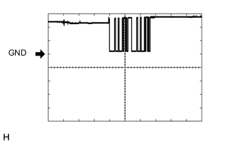
Waveform 1 (Reference)
Measurement Condition Item Content Tester Connection G37-5 (EFII) - G37-8 (GND) Tool Setting 5 V/DIV., 500 ms./DIV. Condition Within 3 seconds after starter operates and initial combustion occurs, or within 3 seconds after engine switch first turned on (IG) after battery disconnected and connected -
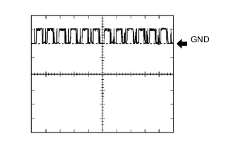
Waveform 2 (Reference)
Measurement Condition Item Content Tester Connection G37-6 (EFIO) - G37-8 (GND) Tool Setting 10 V/DIV., 100 ms./DIV. Condition Engine switch on (IG)
-
-
-
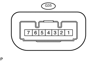
CHECK STEERING LOCK ACTUATOR ASSEMBLY (STEERING LOCK ECU)
-
Disconnect the G35 ECU connector.
-
Measure the voltage and resistance according to the value(s) in the table below.
Terminal No. (Symbol) Wiring Color Terminal Description Condition Specified Condition G35-1 (GND) - Body ground W-B - Body ground Ground Always Below 1 Ω G35-6 (IG2) - G35-1 (GND) W - W-B IG2 signal input Engine switch off → on (IG) Below 1 V → 11 to 14 V G35-7 (B) - Body ground G - Body ground Power source Always 11 to 14 V
-
-
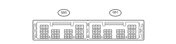
CHECK POWER MANAGEMENT CONTROL ECU
-
Disconnect the G51 ECU connector.
-
Measure the voltage and resistance according to the value(s) in the table below.
Terminal No. (Symbol) Wiring Color Terminal Description Condition Specified Condition G51-1 (AM22) - Body ground B - Body ground Battery power Always 11 to 14 V G51-2 (AM21) - Body ground B - Body ground Battery power Always 11 to 14 V G51-5 (GND2) - Body ground W-B - Body ground Ground Always Below 1 Ω G51-6 (GND) - Body ground W-B - Body ground Ground Always Below 1 Ω
-
-
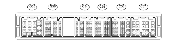
CHECK ECM (for 1GR-FE)
-
Measure the voltage according to the value(s) in the table below.
Terminal No. (Symbol) Wiring Color Terminal Description Condition Specified Condition G56-8 (IMO) - Body ground*1
G56-20 (IMO) - Body ground*2
SB - Body ground ID code box output signal Within 3 seconds after starter operates and initial combustion occurs, or within 3 seconds after engine switch first turned on (IG) after battery disconnected and connected Pulse generation
(see waveform 1)
G56-10 (IMI) - Body ground*1
G56-14 (IMI) - Body ground*2
W - Body ground ID code box input signal Engine switch off → Within 3 seconds after starter operates and initial combustion occurs, or within 3 seconds after engine switch first turned on (IG) after battery disconnected and connected Below 1 V → Pulse generation
(see waveform 2)
-
*1: for Automatic Transmission
-
*2: for Manual Transmission
-
-
Inspect using an oscilloscope.
-
Waveform 1 (Reference)
Measurement Condition Item Content Tester Connection G56-8 (IMO) - Body ground*1
G56-20 (IMO) - Body ground*2
Tool Setting 5 V/DIV., 500 ms./DIV. Condition Within 3 seconds after starter operates and initial combustion occurs, or within 3 seconds after engine switch first turned on (IG) after battery disconnected and connected
-
*1: for Automatic Transmission
-
*2: for Manual Transmission
-
-
Waveform 2 (Reference)
Measurement Condition Item Content Tester Connection G56-10 (IMI) - Body ground*1
G56-14 (IMI) - Body ground*2
Tool Setting 10 V/DIV., 100 ms./DIV. Condition Within 3 seconds after starter operates and initial combustion occurs, or within 3 seconds after engine switch first turned on (IG) after battery disconnected and connected
-
*1: for Automatic Transmission
-
*2: for Manual Transmission
-
-
-
-
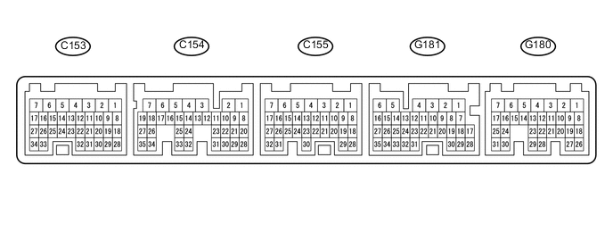
CHECK ECM (for 2TR-FE)
-
Measure the voltage according to the value(s) in the table below.
Terminal No. (Symbol) Wiring Color Terminal Description Condition Specified Condition G181-9 (IMO) - Body ground SB - Body ground ID code box output signal Within 3 seconds after starter operates and initial combustion occurs, or within 3 seconds after engine switch first turned on (IG) after battery disconnected and connected Pulse generation
(see waveform 1)
G181-10 (IMI) - Body ground W - Body ground ID code box input signal Engine switch off → Within 3 seconds after starter operates and initial combustion occurs, or within 3 seconds after engine switch first turned on (IG) after battery disconnected and connected Below 1 V → Pulse generation
(see waveform 2)
-
Inspect using an oscilloscope.
-
Waveform 1 (Reference)
Measurement Condition Item Content Tester Connection G181-9 (IMO) - Body ground Tool Setting 5 V/DIV., 500 ms./DIV. Condition Within 3 seconds after starter operates and initial combustion occurs, or within 3 seconds after engine switch first turned on (IG) after battery disconnected and connected -
Waveform 2 (Reference)
Measurement Condition Item Content Tester Connection G181-10 (IMI) - Body ground Tool Setting 10 V/DIV., 100 ms./DIV. Condition Within 3 seconds after starter operates and initial combustion occurs, or within 3 seconds after engine switch first turned on (IG) after battery disconnected and connected
-
-
-
CHECK ECM (for 1KD-FTV)

-
Measure the voltage according to the value(s) in the table below.
Terminal No. (Symbol) Wiring Color Terminal Description Condition Specified Condition G58-29 (IMO) - Body ground SB - Body ground ID code box output signal Within 3 seconds after starter operates and initial combustion occurs, or within 3 seconds after engine switch first turned on (IG) after battery disconnected and connected Pulse generation
(see waveform 1)
G58-28 (IMI) - Body ground W - Body ground ID code box input signal Engine switch off → Within 3 seconds after starter operates and initial combustion occurs, or within 3 seconds after engine switch first turned on (IG) after battery disconnected and connected Below 1 V → Pulse generation
(see waveform 2)
-
Inspect using an oscilloscope.
-
Waveform 1 (Reference)
Measurement Condition Item Content Tester Connection G58-29 (IMO) - Body ground Tool Setting 5 V/DIV., 500 ms./DIV. Condition Within 3 seconds after starter operates and initial combustion occurs, or within 3 seconds after engine switch first turned on (IG) after battery disconnected and connected -
Waveform 2 (Reference)
Measurement Condition Item Content Tester Connection G58-28 (IMI) - Body ground Tool Setting 10 V/DIV., 100 ms./DIV. Condition Within 3 seconds after starter operates and initial combustion occurs, or within 3 seconds after engine switch first turned on (IG) after battery disconnected and connected
-
-
-
CHECK ECM (for 1GD-FTV)
-
Measure the voltage according to the value(s) in the table below.
Terminal No. (Symbol) Wiring Color Terminal Description Condition Specified Condition G185-17 (IMO) - Body ground SB - Body ground ID code box output signal Within 3 seconds after starter operates and initial combustion occurs, or within 3 seconds after engine switch first turned on (IG) after battery disconnected and connected Pulse generation
(see waveform 1)
G185-16 (IMI) - Body ground W - Body ground ID code box input signal Engine switch off → Within 3 seconds after starter operates and initial combustion occurs, or within 3 seconds after engine switch first turned on (IG) after battery disconnected and connected Below 1 V → Pulse generation
(see waveform 2)
-
Inspect using an oscilloscope.
-
Waveform 1 (Reference)
Measurement Condition Item Content Tester Connection G185-17 (IMO) - Body ground Tool Setting 5 V/DIV., 500 ms./DIV. Condition Within 3 seconds after starter operates and initial combustion occurs, or within 3 seconds after engine switch first turned on (IG) after battery disconnected and connected -
Waveform 2 (Reference)
Measurement Condition Item Content Tester Connection G185-16 (IMI) - Body ground Tool Setting 10 V/DIV., 100 ms./DIV. Condition Within 3 seconds after starter operates and initial combustion occurs, or within 3 seconds after engine switch first turned on (IG) after battery disconnected and connected
-
-