ENTRY AND START SYSTEM(for Start Function) Power Source Mode does not Change to ON (IG)
DESCRIPTION
When the engine switch is pushed with the key in the cabin, the power management control ECU receives signals to switch the power source mode.
WIRING DIAGRAM
Refer to "Power Source Mode does not Change to on (IG and ACC)" Click here.
CAUTION / NOTICE / HINT
Note
-
When using the intelligent tester with the engine switch off to troubleshoot: Connect the intelligent tester to the vehicle and turn a courtesy light switch on and off at 1.5 second intervals until communication between the intelligent tester and vehicle begins.
-
Before performing the inspection, check that there are no problems related to the CAN communication system and LIN communication system.
-
Inspect the fuses for circuits related to this system before performing the following inspection procedure.
PROCEDURE
-
CHECK HARNESS AND CONNECTOR (BATTERY - POWER MANAGEMENT CONTROL ECU)
-
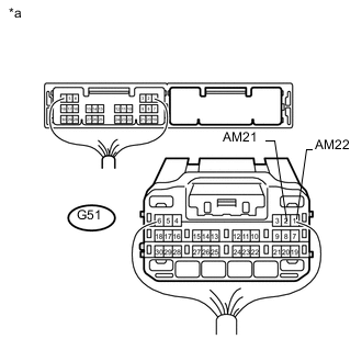
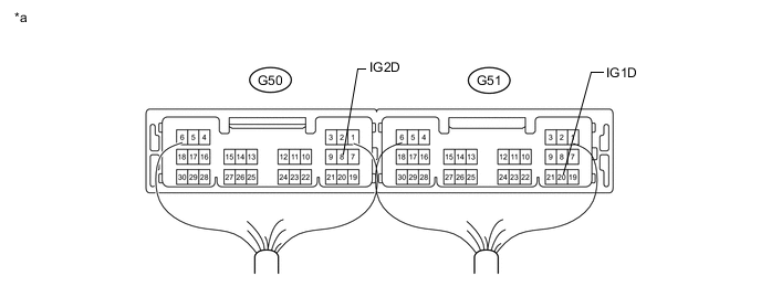
Text in Illustration *a Rear view of wire harness connector
(to Power Management Control ECU)
Disconnect the G51 power management control ECU connector.
-
Measure the voltage according to the value(s) in the table below.
Standard Voltage Tester Connection Condition Specified Condition G51-2 (AM21) - Body ground Always 9.5 to 14 V G51-1 (AM22) - Body ground
NG 
REPAIR OR REPLACE HARNESS OR CONNECTOR
OK 
-
-
CHECK HARNESS AND CONNECTOR (POWER MANAGEMENT CONTROL ECU - BODY GROUND)
-
Disconnect the G51 power management control ECU connector.
-
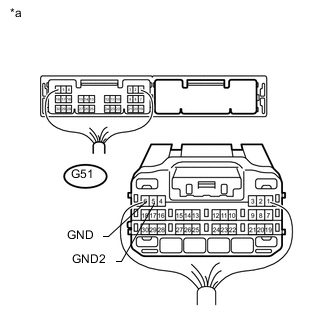
Text in Illustration *a Rear view of wire harness connector
(to Power Management Control ECU)
Measure the resistance according to the value(s) in the table below.
Standard Resistance Tester Connection Condition Specified Condition G51-6 (GND) - Body ground Always Below 1 Ω G51-5 (GND2) - Body ground
NG
REPAIR OR REPLACE HARNESS OR CONNECTOR
OK
-
-
INSPECT NO. 1 INTEGRATION RELAY (IG2 RELAY)
-
Remove the No. 1 integration relay.
-
Measure the resistance according to the value(s) in the table below.
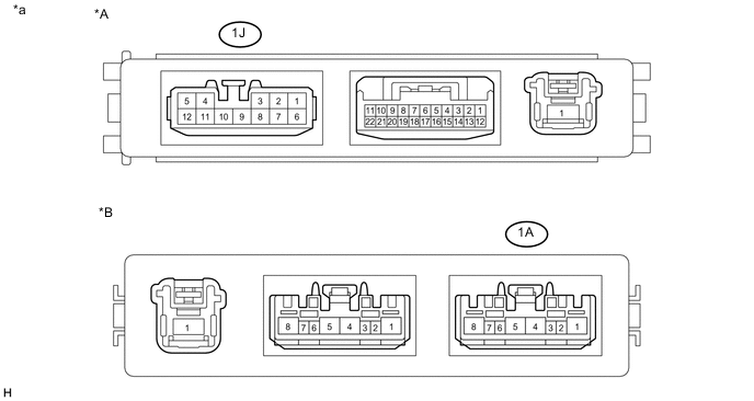
Text in Illustration *A for 1GD-FTV (w/ Urea SCR System) *B except 1GD-FTV (w/ Urea SCR System) *a Component without harness connected
(No. 1 Integration Relay)
- - Standard Resistance for 1GD-FTV (w/ Urea SCR System): Tester Connection Condition Specified Condition 1J-6 - 1J-3 20°C (68°F) 500 to 750Ω except 1GD-FTV (w/ Urea SCR System): Tester Connection Condition Specified Condition 1A-1 - 1A-3 20°C (68°F) 255 to 387 Ω
NG
REPLACE NO. 1 INTEGRATION RELAY
OK
-
-
INSPECT DRIVER SIDE JUNCTION BLOCK ASSEMBLY (IG1 NO. 1, IG1 NO. 2 AND IG1 NO. 3 RELAYS)
-
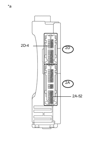
Text in Illustration *a Component without harness connected
(Driver Side Junction Block Assembly)
Remove the driver side junction block assembly.
-
Measure the resistance according to the value(s) in the table below.
Standard Resistance Tester Connection Condition Specified Condition 2A-52 - 2D-4 20°C (68°F) 101.25 to 123.75 Ω
NG
REPLACE MAIN BODY ECU (DRIVER SIDE JUNCTION BLOCK ASSEMBLY)
OK
-
-
CHECK HARNESS AND CONNECTOR (POWER MANAGEMENT CONTROL ECU - DRIVER SIDE JUNCTION BLOCK ASSEMBLY)
-
Disconnect the G51 power management control ECU connector.
-
Disconnect the 2A driver side junction block assembly connector.
-
Measure the resistance according to the value(s) in the table below.
Standard Resistance Tester Connection Condition Specified Condition G51-20 (IG1D) - 2A-52 Always Below 1 Ω G51-20 (IG1D) - Body ground Always 10 kΩ or higher
NG
REPAIR OR REPLACE HARNESS OR CONNECTOR
OK
-
-
CHECK HARNESS AND CONNECTOR (DRIVER SIDE JUNCTION BLOCK ASSEMBLY - BODY GROUND)
-
Disconnect the 2D driver side junction block assembly connector.
-
Measure the resistance according to the value(s) in the table below.
Standard Resistance Tester Connection Condition Specified Condition 2D-4 - Body ground Always Below 1 Ω
NG
REPAIR OR REPLACE HARNESS OR CONNECTOR
OK
-
-
CHECK HARNESS AND CONNECTOR (POWER MANAGEMENT CONTROL ECU - NO. 1 INTEGRATION RELAY)
-
Disconnect the G50 power management control ECU connector.
-
Disconnect the 1J*1 or 1A*2 No. 1 integration relay connector.
-
*1: for 1GD-FTV (w/ Urea SCR System)
-
*2: except 1GD-FTV (w/ Urea SCR System)
-
-
Measure the resistance according to the value(s) in the table below.
Standard Resistance for 1GD-FTV (w/ Urea SCR System): Tester Connection Condition Specified Condition G50-8 (IG2D) - 1J-6 Always Below 1 Ω G50-8 (IG2D) - Body ground Always 10 kΩ or higher except 1GD-FTV (w/ Urea SCR System): Tester Connection Condition Specified Condition G50-8 (IG2D) - 1A-1 Always Below 1 Ω G50-8 (IG2D) - Body ground Always 10 kΩ or higher
NG
REPAIR OR REPLACE HARNESS OR CONNECTOR
OK
-
-
CHECK HARNESS AND CONNECTOR (NO. 1 INTEGRATION RELAY - BODY GROUND)
-
Disconnect the 1J*1 or 1A*2 No. 1 integration relay connector.
-
*1: for 1GD-FTV (w/ Urea SCR System)
-
*2: except 1GD-FTV (w/ Urea SCR System)
-
-
Measure the resistance according to the value(s) in the table below.
Standard Resistance for 1GD-FTV (w/ Urea SCR System): Tester Connection Condition Specified Condition 1J-3 - Body ground Always Below 1 Ω except 1GD-FTV (w/ Urea SCR System): Tester Connection Condition Specified Condition 1A-3 - Body ground Always Below 1 Ω
NG
REPAIR OR REPLACE HARNESS OR CONNECTOR
OK
-
-
CHECK POWER MANAGEMENT CONTROL ECU
-
Install the No. 1 integration relay.
-
Install the driver side junction block assembly.
-
Connect the power management control ECU connectors.
Text in Illustration *a Component with harness connected
(Power Management Control ECU)
- - -
Measure the voltage according to the value(s) in the table below.
Standard Voltage Tester Connection Switch Condition Specified Condition G50-8 (IG2D) - Body ground Engine switch off Below 1 V Engine switch on (IG) ((Voltage at terminal AM21 or AM22) minus 2.0 V) or higher G51-20 (IG1D) - Body ground Engine switch off Below 1 V Engine switch on (IG) ((Voltage at terminal AM21 or AM22) minus 2.0 V) or higher
NG
REPLACE POWER MANAGEMENT CONTROL ECU Click here
OK
-
-
CONFIRM TEST
-
Check that the power source mode changes to on (ACC) and on (IG) when operating the engine switch.
OK The power source mode changes to on (ACC) and on (IG) in response to the operation of the engine switch.
OK
USE SIMULATION METHOD TO CHECK Click here
NG
CHECK RELAY CONTACT SIDE CIRCUIT
-