ENTRY AND START SYSTEM(for Entry Function) TERMINALS OF ECU
-
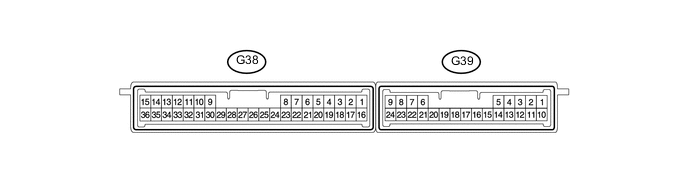
CHECK CERTIFICATION ECU
-
Disconnect the G38 ECU connector.
-
Measure the voltage and resistance according to the value(s) in the table below.
Terminal No. (Symbol) Wiring Color Terminal Description Condition Specified Condition G38-1 (+B) - G38-15 (E) V - W-B +B power supply Always 11 to 14 V G38-15 (E) - Body ground W-B - Body ground Ground Always Below 1 Ω G38-16 (IG) - G38-15 (E) W - W-B IG power supply Engine switch off → on (IG) Below 1 V →11 to 14 V G38-17 (CUTB) - G38-15 (E) L - W-B +B power supply Always 11 to 14 V If the result is not as specified, there may be a malfunction on the wire harness side.
-
Reconnect the G38 ECU connector.
-
Measure the voltage according to the value(s) in the table below.
Terminal No. (Symbol) Wiring Color Terminal Description Condition Specified Condition G38-3 (CLG1) - G38-15 (E) R - W-B Electrical key antenna (for driver side) sensor signal Engine switch off, all doors closed, key not in cabin and transmitter lock switch not pressed → pressed No pulse generation → Pulse generation G38-4 (CG1B) - G38-15 (E) G - W-B Electrical key antenna (for driver side) sensor signal Engine switch off, all doors closed, key not in cabin and transmitter lock switch not pressed → pressed No pulse generation → Pulse generation G38-5 (CLG2) - G38-15 (E) B - W-B Electrical key antenna (for front passenger side) sensor signal Engine switch off, all doors closed, key not in cabin and transmitter lock switch not pressed → pressed No pulse generation → Pulse generation G38-6 (CG2B) - G38-15 (E) W - W-B Electrical key antenna (for front passenger side) sensor signal Engine switch off, all doors closed, key not in cabin and transmitter lock switch not pressed → pressed No pulse generation → Pulse generation G38-7 (CLG5) - G38-15 (E) R - W-B Indoor No. 1 electrical key antenna (front floor) sensor signal Engine switch off, all doors closed, key not in cabin and lock sensor off → on No pulse generation → Pulse generation G38-8 (CG5B) - G38-15 (E) W - W-B Indoor No. 1 electrical key antenna (front floor) sensor signal Engine switch off, all doors closed, key not in cabin and lock sensor off → on No pulse generation → Pulse generation G38-18 (TSW1) - G38-15 (E) LG - W-B Entry lock sensor (for driver side) detection signal Engine switch off, all doors closed and lock sensor (for driver side) off → on Pulse generation → Below 2 V G38-19 (TSW2) - G38-15 (E) V - W-B Entry lock sensor (for front passenger side) detection signal Engine switch off, all doors closed and lock sensor (for front passenger side) off → on Pulse generation → Below 2 V G38-20 (SEN1) - G38-15 (E) W - W-B Entry unlock sensor (for driver side) detection signal Engine switch off, all doors locked, key not sufficiently close to vehicle and unlock sensor (for driver side) off → on Pulse generation → Below 2 V G38-21 (SEN2) - G38-15 (E) L - W-B Entry unlock sensor (for front passenger side) detection signal Engine switch off, all doors locked, key not sufficiently close to vehicle and unlock sensor (for front passenger side) off → on Pulse generation → Below 2 V G38-22 (TSW5) - Body ground G - Body ground Luggage electrical key switch signal Unlock switch off → on Pulse generation → Below 1 V G38-23 (TSW6) - Body ground L - Body ground Luggage electrical key switch signal Lock switch off → on Pulse generation → Below 1 V G38-24 (CLG6) - G38-15 (E) Y - W-B Indoor No. 2 electrical key antenna (rear floor) sensor signal Engine switch off, all doors closed, key not in cabin and lock sensor off → on No pulse generation → Pulse generation G38-25 (CG6B) - G38-15 (E) W - W-B Indoor No. 2 electrical key antenna (rear floor) sensor signal Engine switch off, all doors closed, key not in cabin and lock sensor off → on No pulse generation → Pulse generation G38-26 (CLG7) - G38-15 (E) LG - W-B Indoor No. 3 electrical key antenna (inside luggage) sensor signal Engine switch off, all doors closed, key not in cabin and lock sensor off → on No pulse generation → Pulse generation G38-27 (CG7B) - G38-15 (E) L - W-B Indoor No. 3 electrical key antenna (inside luggage) sensor signal Engine switch off, all doors closed, key not in cabin and lock sensor off → on No pulse generation → Pulse generation G38-32 (POS1) - G38-15 (E) R - W-B Entry unlock sensor (for driver side) output signal Engine switch off → on (IG) 9 to 14 V → Below 2 V G38-33 (POS2) - G38-15 (E) R - W-B Entry unlock sensor (for front passenger side) output signal Engine switch off → on (IG) 9 to 14 V → Below 2 V G39-5 (RCO) - G38-15 (E) L - W-B Door control receiver power source Engine switch off and transmitter switch not pressed → pressed Below 1 V → 4.5 to 5.5 V G39-15 (RDA) - G38-15 (E) G - W-B Door control receiver data input signal Engine switch off 11 to 14 V pulse generation at regular intervals G39-16 (RSSI) - G38-15 (E) P - W-B Door control receiver electric wave existence signal All doors closed, all doors locked and transmitter switch not pressed → pressed 11 to 14 V → Below 2 V G39-19 (CLG8) - G38-15 (E) B - W-B Electrical key antenna (outside luggage) sensor signal Engine switch off, all doors closed and unlock switch off → on No pulse generation → Pulse generation G39-20 (CG8B) - G38-15 (E) W - W-B Electrical key antenna (outside luggage) sensor signal Engine switch off, all doors closed and unlock switch off → on No pulse generation → Pulse generation If the result is not as specified, the certification ECU may have a malfunction.
-
-
CHECK DRIVER SIDE JUNCTION BLOCK ASSEMBLY AND MAIN BODY ECU (MULTIPLEX NETWORK BODY ECU)
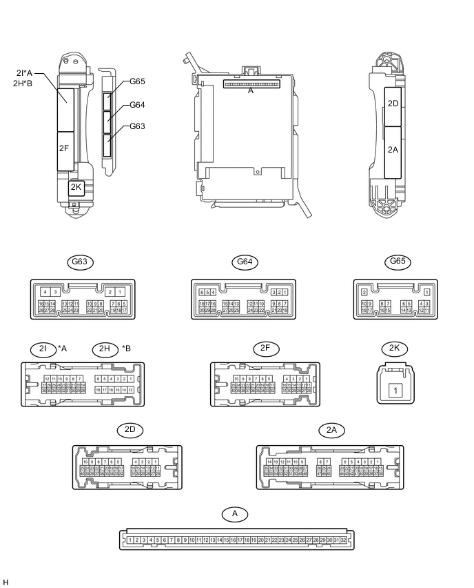
Text in Illustration *A for LHD *B for RHD
-
Remove the main body ECU Click here.
-
Measure the voltage and resistance according to the value(s) in the table below.
Terminal No. (Symbol) Wiring Color Terminal Description Condition Specified Condition A-30 (BECU) - Body ground - Auxiliary battery power supply Always 11 to 14 V A-31 (ALTB) - Body ground - Auxiliary battery power supply Always 11 to 14 V A-32 (IG) - Body ground - Engine switch power supply Engine switch on (IG) 11 to 14 V A-32 (IG) - Body ground - Engine switch power supply Engine switch off Below 1 V A-29 (ACC) - Body ground - ACC power supply Engine switch on (ACC) 11 to 14 V A-29 (ACC) - Body ground - ACC power supply Engine switch off Below 1 V A-11 (GND1) - Body ground - Ground Always Below 1 Ω G63-3 (GND2) - Body ground W-B - Body ground Ground Always Below 1 Ω If the result is not as specified, there may be a malfunction in the wire harness.
-
Install the main body ECU Click here.
-
Measure the voltage according to the value(s) in the table below.
Terminal No. (Symbol) Wiring Color Terminal Description Condition Specified Condition 2I-27 (FLCY) - Body ground*1 R - Body ground Front door LH courtesy switch input Front door LH open Below 1 V 2I-27 (FLCY) - Body ground*1 R - Body ground Front door LH courtesy switch input Front door LH closed 11 to 14 V 2D-31 (FLCY) - Body ground*2 R - Body ground Front door LH courtesy switch input Front door LH open Below 1 V 2D-31 (FLCY) - Body ground*2 R - Body ground Front door LH courtesy switch input Front door LH closed 11 to 14 V 2D-15 (FRCY) - Body ground*1 B - Body ground Front door RH courtesy switch input Front door RH open Below 1 V 2D-15 (FRCY) - Body ground*1 B - Body ground Front door RH courtesy switch input Front door RH closed 11 to 14 V 2H-26 (FRCY) - Body ground*2 B - Body ground Front door RH courtesy switch input Front door RH open Below 1 V 2H-26 (FRCY) - Body ground*2 B - Body ground Front door RH courtesy switch input Front door RH closed 11 to 14 V G65-3 (LCTY) - Body ground*3 V - Body ground Rear door LH courtesy light switch input Rear door LH open Below 1 V G65-3 (LCTY) - Body ground*3 V - Body ground Rear door LH courtesy light switch input Rear door LH closed 11 to 14 V G64-6 (RCTY) - Body ground*3 R - Body ground Rear door RH courtesy light switch input Rear door RH open Below 1 V G64-6 (RCTY) - Body ground*3 R - Body ground Rear door RH courtesy light switch input Rear door RH closed 11 to 14 V G64-19 (BCTY) - Body ground G - Body ground Back door courtesy light switch input Back door open Below 1 V G64-19 (BCTY) - Body ground G - Body ground Back door courtesy light switch input Engine switch off, all doors closed and back door closed Pulse generation (see waveform 1 or 2) G64-1 (GCTY) - Body ground*4 V - Body ground Glass hatch courtesy switch input Glass hatch open Below 1 V G64-1 (GCTY) - Body ground*4 V - Body ground Glass hatch courtesy switch input Engine switch off, all doors closed and glass hatch closed Pulse generation (see waveform 3 or 4) G64-7 (LSFL) - Body ground G - Body ground Front door LH lock position switch input Front door LH unlocked Below 1 V G64-7 (LSFL) - Body ground G - Body ground Front door LH lock position switch input Engine switch off, all doors closed and front door LH locked Pulse generation (see waveform 5 or 6) G64-18 (LSFR) - Body ground G - Body ground Front door RH lock position switch input Front door RH unlocked Below 1 V G64-18 (LSFR) - Body ground G - Body ground Front door RH lock position switch input Engine switch off, all doors closed and front door RH locked Pulse generation (see waveform 7 or 8) 2I-25 (LSWL) - Body ground*1, *3 B - Body ground Rear door LH lock position switch input Rear door LH unlocked Below 1 V 2I-25 (LSWL) - Body ground*1, *3 B - Body ground Rear door LH lock position switch input Engine switch off, all doors closed and rear door LH locked Pulse generation (see waveform 9 or 10) 2D-16 (LSWL) - Body ground*2, *3 B - Body ground Rear door LH lock position switch input Rear door LH unlocked Below 1 V 2D-16 (LSWL) - Body ground*2, *3 B - Body ground Rear door LH lock position switch input Engine switch off, all doors closed and rear door LH locked Pulse generation (see waveform 11 or 12) G63-2 (LSWR) - Body ground*3 V - Body ground Rear door RH lock position switch input Rear door RH unlocked Below 1 V G63-2 (LSWR) - Body ground*3 V - Body ground Rear door RH lock position switch input Engine switch off, all doors closed and rear door RH locked Pulse generation (see waveform 13 or 14) G65-13 (LSWB) - Body ground SB - Body ground Back door lock position switch input Back door lock unlocked Below 1 V G65-13 (LSWB) - Body ground SB - Body ground Back door lock position switch input Engine switch off, all doors closed and back door locked Pulse generation (see waveform 15 or 16)
-
*1: for LHD
-
*2: for RHD
-
*3: for 5 Door
-
*4: w/ Glass Hatch Opener System
If the result is not as specified, the main body ECU or driver side junction block assembly may have a malfunction.
-
-
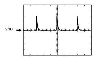
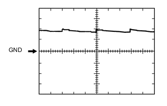
Using an oscilloscope, check waveform 1.
Waveform 1 (Reference) Item Content Terminal No. (Symbol) G64-19 (BCTY) - Body ground Tool Setting 5 V/DIV., 20 ms/DIV. Condition Engine switch off, all doors closed and back door closed -
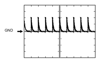
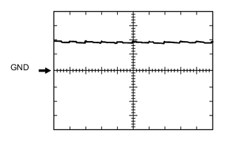
Using an oscilloscope, check waveform 2.
Waveform 2 (Reference) Item Content Terminal No. (Symbol) G64-19 (BCTY) - Body ground Tool Setting 5 V/DIV., 20 ms/DIV. Condition Engine switch off, all doors closed and back door closed -
Using an oscilloscope, check waveform 3.
Waveform 3 (Reference) Item Content Terminal No. (Symbol) G64-1 (GCTY) - Body ground Tool Setting 5 V/DIV., 20 ms/DIV. Condition Engine switch off, all doors closed and glass hatch closed -
Using an oscilloscope, check waveform 4.
Waveform 4 (Reference) Item Content Terminal No. (Symbol) G64-1 (GCTY) - Body ground Tool Setting 5 V/DIV., 20 ms/DIV. Condition Engine switch off, all doors closed and glass hatch closed -
Using an oscilloscope, check waveform 5.
Waveform 5 (Reference) Item Content Terminal No. (Symbol) G64-7 (LSFL) - Body ground Tool Setting 5 V/DIV., 20 ms/DIV. Condition Engine switch off, all doors closed and front door LH locked -
Using an oscilloscope, check waveform 6.
Waveform 6 (Reference) Item Content Terminal No. (Symbol) G64-7 (LSFL) - Body ground Tool Setting 5 V/DIV., 20 ms/DIV. Condition Engine switch off, all doors closed and front door LH locked -
Using an oscilloscope, check waveform 7.
Waveform 7 (Reference) Item Content Terminal No. (Symbol) G64-18 (LSFR) - Body ground Tool Setting 5 V/DIV., 20 ms/DIV. Condition Engine switch off, all doors closed and front door RH locked -
Using an oscilloscope, check waveform 8.
Waveform 8 (Reference) Item Content Terminal No. (Symbol) G64-18 (LSFR) - Body ground Tool Setting 5 V/DIV., 20 ms/DIV. Condition Engine switch off, all doors closed and front door RH locked -
Using an oscilloscope, check waveform 9.
Waveform 9 (Reference) Item Content Terminal No. (Symbol) 2I-25 (LSWL) - Body ground Tool Setting 5 V/DIV., 20 ms/DIV. Condition Engine switch off, all doors closed and rear door LH locked -
Using an oscilloscope, check waveform 10.
Waveform 10 (Reference) Item Content Terminal No. (Symbol) 2I-25 (LSWL) - Body ground Tool Setting 5 V/DIV., 20 ms/DIV. Condition Engine switch off, all doors closed and rear door LH locked -
Using an oscilloscope, check waveform 11.
Waveform 11 (Reference) Item Content Terminal No. (Symbol) 2D-16 (LSWL) - Body ground Tool Setting 5 V/DIV., 20 ms/DIV. Condition Engine switch off, all doors closed and rear door LH locked -
Using an oscilloscope, check waveform 12.
Waveform 12 (Reference) Item Content Terminal No. (Symbol) 2D-16 (LSWL) - Body ground Tool Setting 5 V/DIV., 20 ms/DIV. Condition Engine switch off, all doors closed and rear door LH locked -
Using an oscilloscope, check waveform 13.
Waveform 13 (Reference) Item Content Terminal No. (Symbol) G63-2 (LSWR) - Body ground Tool Setting 5 V/DIV., 20 ms/DIV. Condition Engine switch off, all doors closed and rear door RH locked -
Using an oscilloscope, check waveform 14.
Waveform 14 (Reference) Item Content Terminal No. (Symbol) G63-2 (LSWR) - Body ground Tool Setting 5 V/DIV., 20 ms/DIV. Condition Engine switch off, all doors closed and rear door RH locked -
Using an oscilloscope, check waveform 15.
Waveform 15 (Reference) Item Content Terminal No. (Symbol) G65-13 (LSWB) - Body ground Tool Setting 5 V/DIV., 20 ms/DIV. Condition Engine switch off, all doors closed and back door locked -
Using an oscilloscope, check waveform 16.
Waveform 16 (Reference) Item Content Terminal No. (Symbol) G65-13 (LSWB) - Body ground Tool Setting 5 V/DIV., 20 ms/DIV. Condition Engine switch off, all doors closed and back door locked
-