KEY REMINDER WARNING SYSTEM TERMINALS OF ECU
-
CHECK DRIVER SIDE JUNCTION BLOCK ASSEMBLY AND MAIN BODY ECU (MULTIPLEX NETWORK BODY ECU) (for 5L-E)
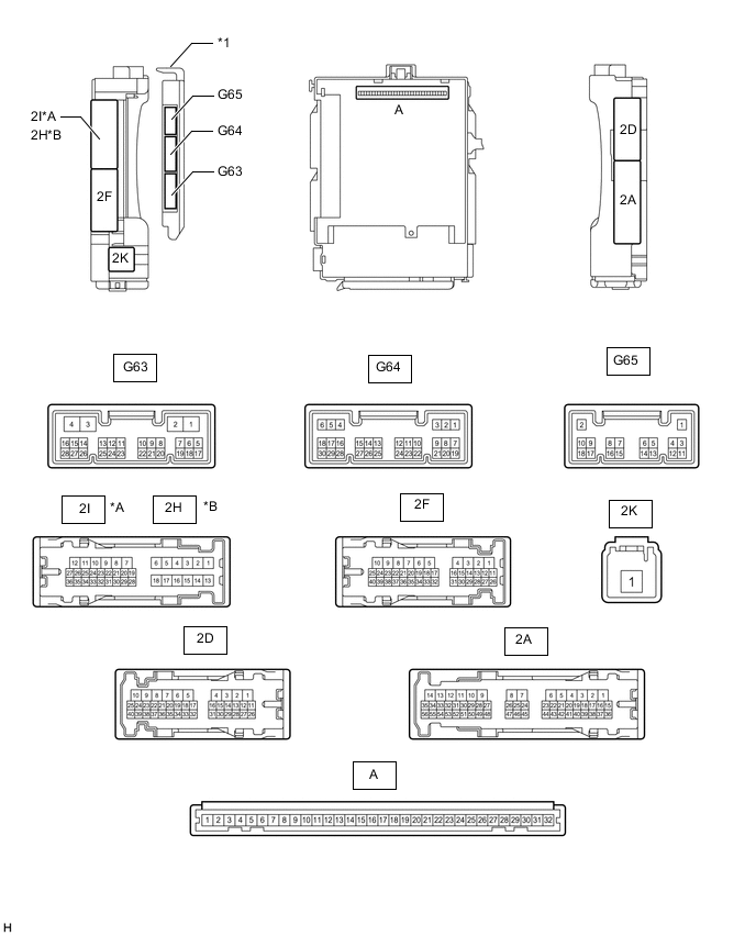
*A for LHD *B for RHD *1 Main Body ECU (Multiplex Network Body ECU) - -
-
Remove the main body ECU (multiplex network body ECU) from the driver side junction block assembly.
-
Connect the driver side junction block assembly connectors.
-
Measure the voltage and resistance according to the value(s) in the table below.
Terminal No. (Symbol) Wiring Color Terminal Description Condition Specified Condition A-30 (BECU) - Body ground - Battery power supply Always 11 to 14 V A-31 (ALTB) - Body ground - Battery power supply Always 11 to 14 V A-32 (IG) - Body ground - Ignition switch power supply Ignition switch ON 11 to 14 V Ignition switch off Below 1 V A-29 (ACC) - Body ground - ACC power supply Ignition switch ACC 11 to 14 V Ignition switch off Below 1 V A-11 (GND1) - Body ground - Ground Always Below 1 Ω G64-17 (KSW) - Body ground G - Body ground Unlock warning switch No key in ignition key cylinder 10 kΩ or higher Key inserted in ignition key cylinder Below 1 Ω -
Install the main body ECU (multiplex network body ECU).
-
Measure the voltage according to the value(s) in the table below.
Terminal No. (Symbol) Wiring Color Terminal Description Condition Specified Condition 2I-27 (FLCY) - Body ground*1 R - Body ground Front door LH courtesy switch input Front door LH open Below 1 V Front door LH closed 11 to 14 V 2H-26 (FRCY) - Body ground*2 B - Body ground Front door RH courtesy switch input Front door RH open Below 1 V Front door RH closed 11 to 14 V
-
*1: for LHD
-
*2: for RHD
-
-
-
CHECK DRIVER SIDE JUNCTION BLOCK ASSEMBLY AND MAIN BODY ECU (MULTIPLEX NETWORK BODY ECU) (except 5L-E)
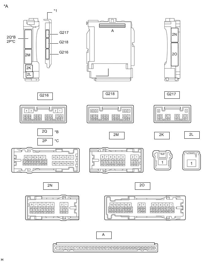
*A Main Body ECU (Multiplex Network Body ECU) with 3 connectors *B for LHD *C for RHD - - *1 Main Body ECU (Multiplex Network Body ECU) - - 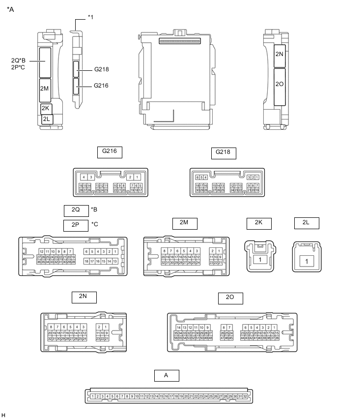
*A Main Body ECU (Multiplex Network Body ECU) with 2 connectors *B for LHD *C for RHD - - *1 Main Body ECU (Multiplex Network Body ECU) - -
-
Remove the main body ECU (multiplex network body ECU) from the driver side junction block assembly.
-
Connect the driver side junction block assembly connector.
-
Measure the voltage and resistance according to the value(s) in the table below.
Terminal No. (Symbol) Wiring Color Terminal Description Condition Specified Condition A-32 (IG) - Body ground - Ignition power supply Ignition switch ON 11 to 14 V Ignition switch off Below 1 V A-31 (BECU) - Body ground - Battery power supply Always 11 to 14 V A-30 (ACC) - Body ground - ACC power supply Ignition switch ACC 11 to 14 V Ignition switch off Below 1 V A-11 (GND1) - Body ground - Ground Always Below 1 Ω A-3 (KSW) - Body ground - Unlock warning switch No key in ignition key cylinder 10 kΩ or higher Key inserted in ignition key cylinder Below 1 Ω -
Install the main body ECU (multiplex network body ECU).
-
Measure the voltage according to the value(s) in the table below.
Terminal No. (Symbol) Wiring Color Terminal Description Condition Specified Condition G218-6 (FLCY) - Body ground*1 R - Body ground Front door courtesy light switch assembly LH signal Front door LH open Below 1 V Front door LH closed 11 to 14 V G218-27 (FRCY) - Body ground*2 B - Body ground Front door courtesy light switch assembly RH signal Front door RH open Below 1 V Front door RH closed 11 to 14 V
-
*1: for LHD
-
*2: for RHD
-
-