FRONT DOOR LOCK INSPECTION
PROCEDURE
-
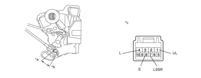
INSPECT FRONT DOOR LOCK ASSEMBLY LH (w/o Double Locking System)
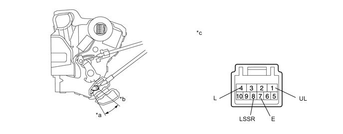
Text in Illustration *a Lock *b Unlock *c Component without harness connected
(Front Door Lock Assembly LH)
- -
-
Check the door lock motor operation.
-
Apply battery voltage to the motor connector and check the operation of the front door lock motor.
OK Measurement Condition Specified Condition Battery positive (+) → 4 (L)
Battery negative (-) → 1 (UL)
Lock Battery positive (+) → 1 (UL)
Battery negative (-) → 4 (L)
Unlock
-
If the result is not as specified, replace the front door lock assembly.
-
-
-
Check the detection switch.
-
Measure the resistance according to the value(s) in the table below.
Standard Resistance Tester Connection Switch Condition Specified Condition 8 (LSSR) - 7 (E) Lock 10 kΩ or higher 8 (LSSR) - 7 (E) Unlock Below 1 Ω
-
If the result is not as specified, replace the front door lock assembly.
-
-
-
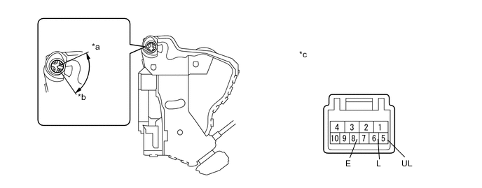
for LHD:
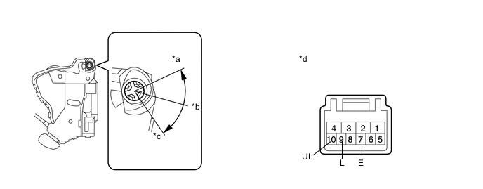
Text in Illustration *a Lock *b Off *c Unlock *d Component without harness connected
(Front Door Lock Assembly LH)
-
Check the door lock and unlock switch.
-
Measure the resistance according to the value(s) in the table below.
Standard Resistance Tester Connection Switch Condition Specified Condition 9 (L) - 7 (E) Lock Below 1 Ω 9 (L) - 7 (E)
10 (UL) - 7 (E)
OFF 10 kΩ or higher 10 (UL) - 7 (E) Unlock Below 1 Ω
-
If the result is not as specified, replace the front door lock assembly.
-
-
-
-
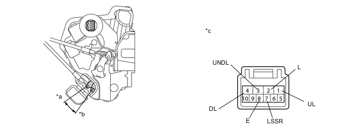
INSPECT FRONT DOOR LOCK ASSEMBLY LH (w/ Double Locking System)
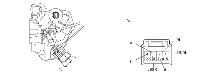
Text in Illustration *a Lock *b Unlock *c Component without harness connected
(Front Door Lock Assembly LH)
- -
-
Check the door lock motor operation.
-
Apply battery voltage to the motor connector and check the operation of the door lock motor.
OK Measurement Condition Specified Condition Battery positive (+) → 4 (L)
Battery negative (-) → 3 (UL)
Lock Battery positive (+) → 3 (UL)
Battery negative (-) → 4 (L)
Unlock Battery positive (+) → 2 (DL)
Battery negative (-) → 1 (UNDL)
Set Battery positive (+) → 1 (UNDL)
Battery negative (-) → 2 (DL)
Unset
-
If the result is not as specified, replace the front door lock assembly.
-
-
-
Check the detection switch.
-
Measure the resistance according to the value(s) in the table below.
Standard Resistance Tester Connection Switch Condition Specified Condition 8 (LSSR) - 7 (E) Lock 10 kΩ or higher 8 (LSSR) - 7 (E) Unlock Below 1 Ω
-
If the result is not as specified, replace the front door lock assembly.
-
-
-
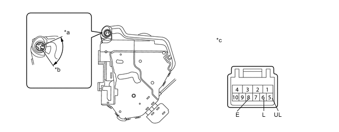
for LHD:
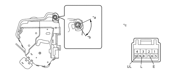
Text in Illustration *a Lock *b Unlock *c Component without harness connected
(Front Door Lock Assembly LH)
- -
-
Check the door lock and unlock switch.
-
Measure the resistance according to the value(s) in the table below.
Standard Resistance Tester Connection Switch Condition Specified Condition 9 (L) - 7 (E) Lock Below 1 Ω 9 (L) - 7 (E)
10 (UL) - 7 (E)
OFF 10 kΩ or higher 10 (UL) - 7 (E) Unlock Below 1 Ω
-
If the result is not as specified, replace the front door lock assembly.
-
-
-
-
INSPECT FRONT DOOR LOCK ASSEMBLY RH (w/o Double Locking System)
Text in Illustration *a Unlock *b Lock *c Component without harness connected
(Front Door Lock Assembly RH)
- -
-
Check the door lock motor operation.
-
Apply battery voltage to the door lock motor connector and check the operation of the door lock motor.
OK Measurement Condition Specified Condition Battery positive (+) → 4 (L)
Battery negative (-) → 1 (UL)
Lock Battery positive (+) → 1 (UL)
Battery negative (-) → 4 (L)
Unlock
-
If the result is not as specified, replace the front door lock assembly.
-
-
-
Check the detection switch.
-
Measure the resistance according to the value(s) in the table below.
Standard Resistance Tester Connection Switch Condition Specified Condition 7 (LSSR) - 8 (E) Lock 10 kΩ or higher 7 (LSSR) - 8 (E) Unlock Below 1 Ω
-
If the result is not as specified, replace the front door lock assembly.
-
-
-
for RHD:
Text in Illustration *a Unlock *b Lock *c Component without harness connected
(Front Door Lock Assembly RH)
- -
-
Check the door lock and unlock switch.
-
Measure the resistance according to the value(s) in the table below.
Standard Resistance Tester Connection Switch Condition Specified Condition 6 (L) - 8 (E) Lock Below 1 Ω 6 (L) - 8 (E)
5 (UL) - 8 (E)
OFF 10 kΩ or higher 5 (UL) - 8 (E) Unlock Below 1 Ω
-
If the result is not as specified, replace the front door lock assembly.
-
-
-
-
INSPECT FRONT DOOR LOCK ASSEMBLY RH (w/ Double Locking System)
Text in Illustration *a Unlock *b Lock *c Component without harness connected
(Front Door Lock Assembly RH)
- -
-
Check the door lock motor operation.
-
Apply battery voltage to the door lock motor connector and check the operation of the door lock motor.
OK Measurement Condition Specified Condition Battery positive (+) → 2 (L)
Battery negative (-) → 1 (UL)
Lock Battery positive (+) → 1 (UL)
Battery negative (-) → 2 (L)
Unlock Battery positive (+) → 4 (DL)
Battery negative (-) → 3 (UNDL)
Set Battery positive (+) → 3 (UNDL)
Battery negative (-) → 4 (DL)
Unset
-
If the result is not as specified, replace the front door lock assembly.
-
-
-
Check the detection switch.
-
Measure the resistance according to the value(s) in the table below.
Standard Resistance Tester Connection Switch Condition Specified Condition 7 (LSSR) - 8 (E) Lock 10 kΩ or higher 7 (LSSR) - 8 (E) Unlock Below 1 Ω
-
If the result is not as specified, replace the front door lock assembly.
-
-
-
for RHD:
Text in Illustration *a Unlock *b Lock *c Component without harness connected
(Front Door Lock Assembly RH)
- -
-
Check the door lock and unlock switch.
-
Measure the resistance according to the value(s) in the table below.
Standard Resistance Tester Connection Switch Condition Specified Condition 6 (L) - 8 (E) Lock Below 1 Ω 6 (L) - 8 (E)
5 (UL) - 8 (E)
OFF 10 kΩ or higher 5 (UL) - 8 (E) Unlock Below 1 Ω
-
If the result is not as specified, replace the front door lock assembly.
-
-
-