WIRELESS DOOR LOCK CONTROL SYSTEM(w/ Entry and Start System) No Answer-Back
DESCRIPTION
In some cases, the wireless door lock control functions are normal but the hazard warning light and/or wireless door lock buzzer answer-back function(s) does not operate. In such cases, hazard warning light and wireless door lock buzzer signal outputs from the main body ECU may be malfunctioning.
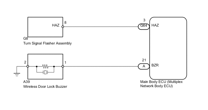
WIRING DIAGRAM
CAUTION / NOTICE / HINT
Note
Start troubleshooting after confirming that the customize status of the answer-back function has been switched on.
PROCEDURE
-
READ VALUE USING INTELLIGENT TESTER (DOOR LOCK POSITION SWITCH)
-
Connect the intelligent tester to the DLC3.
-
Turn the engine switch on (IG).
-
Turn the intelligent tester on.
-
Enter the following menus: Body / Main Body / Data List.
-
Read the Data List according to the display on the intelligent tester.
Main Body Tester Display Measurement Item/Range Normal Condition Diagnostic Note Back Door Lock Pos SW Back door lock position switch status / ON or OFF ON: Back door unlocked
OFF: Back door locked
- FR Door Lock Pos Front RH side door lock position switch signal / UNLOCK or LOCK UNLOCK: Front RH side door unlocked
LOCK: Front RH side door locked
- FL Door Lock Pos Front LH side door lock position switch signal / UNLOCK or LOCK UNLOCK: Front LH side door unlocked
LOCK: Front LH side door locked
- RR-Door Lock Pos SW* Rear RH side door lock position switch signal / ON or OFF ON: Rear RH side door unlocked
OFF: Rear RH side door locked
- RL-Door Lock Pos SW* Rear LH side door lock position switch signal / ON or OFF ON: Rear LH side door unlocked
OFF: Rear LH side door locked
-
-
*: for 5 Door
OK The intelligent tester should display as shown in the table according to door lock operation. Tech Tips
-
Go to POWER DOOR LOCK CONTROL SYSTEM (Proceed to Only Back Door Lock/Unlock Functions do not Operate) Click here.
-
Go to POWER DOOR LOCK CONTROL SYSTEM (Proceed to Only Driver Door Lock/Unlock Functions do not Operate) Click here.
-
Go to POWER DOOR LOCK CONTROL SYSTEM (Proceed to Only Front Passenger Door Lock/Unlock Functions do not Operate) Click here.
-
Go to POWER DOOR LOCK CONTROL SYSTEM (Proceed to Only Rear Door RH Lock/Unlock Functions do not Operate) Click here.
-
Go to POWER DOOR LOCK CONTROL SYSTEM (Proceed to Only Rear Door LH Lock/Unlock Functions do not Operate) Click here.
-
NG 
GO TO POWER DOOR LOCK CONTROL SYSTEM
OK 
-
-
CHECK WIRELESS ANSWER-BACK OPERATION
-
Check the wireless answer-back operation by the wireless door lock control function.
Result Result Proceed to Only hazard warning light answer-back does not occur A Only wireless door lock buzzer answer-back does not occur* B
-
*: w/ Wireless Buzzer Answer-back
-
B 
PERFORM ACTIVE TEST USING INTELLIGENT TESTER (WIRELESS DOOR LOCK BUZZER) Click here
A
-
-
CHECK HAZARD WARNING LIGHT OPERATION
-
Check that the hazard warning lights flash continuously when the hazard warning signal switch is pressed.
OK Hazard warning lights flash continuously.
NG
GO TO LIGHTING SYSTEM Click here
OK
-
-
PERFORM ACTIVE TEST USING INTELLIGENT TESTER (HAZARD WARNING LIGHT)
-
Operate the intelligent tester according to the steps on the display and select "Active Test" Click here.
Main Body Tester Display Test Part Control Range Diagnostic Note Hazard Turn signal flasher relay ON/OFF - OK The hazard warning lights can be turned on and off using the intelligent tester.
OK
REPLACE MAIN BODY ECU (MULTIPLEX NETWORK BODY ECU) Click here
NG
-
-
CHECK HARNESS AND CONNECTOR (TURN SIGNAL FLASHER - MAIN BODY ECU)
-
Disconnect the G8 flasher connector.
-
Disconnect the G64 ECU connector.
-
Measure the resistance according to the value(s) in the table below.
Standard Resistance Tester Connection Condition Specified Condition G8-8 (HAZ) - G64-3 (HAZ) Always Below 1 Ω G8-8 (HAZ) - Body ground Always 10 kΩ or higher
OK
REPLACE MAIN BODY ECU (MULTIPLEX NETWORK BODY ECU) Click here
NG
REPAIR OR REPLACE HARNESS OR CONNECTOR
-
-
PERFORM ACTIVE TEST USING INTELLIGENT TESTER (WIRELESS DOOR LOCK BUZZER)
-
Operate the intelligent tester according to the steps on the display and select "Active Test" Click here.
Main Body Tester Display Test Part Control Range Diagnostic Note Wireless Buzzer Wireless door lock buzzer ON/OFF - OK The wireless door lock buzzer can be turned on and off using the intelligent tester.
OK
REPLACE MAIN BODY ECU (MULTIPLEX NETWORK BODY ECU) Click here
NG
-
-
CHECK HARNESS AND CONNECTOR (WIRELESS DOOR LOCK BUZZER - MAIN BODY ECU)
-
Disconnect the A39 buzzer connector.
-
Remove the main body ECU Click here.
-
Measure the resistance according to the value(s) in the table below.
Standard Resistance Tester Connection Condition Specified Condition A39-1 - A-21 (BZR) Always Below 1 Ω A39-2 - Body ground Always Below 1 Ω A39-1 - Body ground Always 10 kΩ or higher
NG
REPAIR OR REPLACE HARNESS OR CONNECTOR
OK
-
-
REPLACE WIRELESS DOOR LOCK BUZZER
-
Temporarily replace the wireless door lock buzzer with a new or normally functioning one Click here.
NEXT
-
-
CHECK WIRELESS DOOR LOCK BUZZER OPERATION
-
Check that the wireless door lock buzzer sounds by operating the wireless door lock function.
OK Wireless door lock buzzer sounds.
OK
END (WIRELESS DOOR LOCK BUZZER IS DEFECTIVE)
NG
REPLACE MAIN BODY ECU (MULTIPLEX NETWORK BODY ECU) Click here
-