NETWORK GATEWAY ECU REMOVAL
CAUTION / NOTICE / HINT
Tech Tips
-
Use the same procedure for LHD and RHD vehicles.
-
The procedure listed below is for LHD vehicles.
PROCEDURE
-
DISCONNECT CABLE FROM NEGATIVE BATTERY TERMINAL
Note
-
After turning the ignition switch off, waiting time may be required before disconnecting the cable from the battery terminal. Therefore, make sure to read the disconnecting the cable from the battery terminal notice before proceeding with work.
-
When disconnecting the cable, some systems need to be initialized after the cable is reconnected.
-
-
REMOVE DOOR SCUFF PLATE ASSEMBLY RH
-
REMOVE COWL SIDE TRIM BOARD RH
-
REMOVE NO. 2 INSTRUMENT PANEL UNDER COVER SUB-ASSEMBLY
-
REMOVE FRONT DOOR OPENING TRIM WEATHERSTRIP RH
-
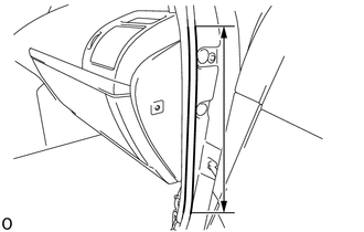
Remove the front door opening trim weatherstrip RH in the range shown in the illustration.
-
-
REMOVE INSTRUMENT SIDE PANEL RH
-
REMOVE INSTRUMENT PANEL ORNAMENT
-
REMOVE GLOVE COMPARTMENT DOOR ASSEMBLY
-
REMOVE NO. 2 AIR DUCT SUB-ASSEMBLY
-
REMOVE WINDSHIELD WIPER RELAY ASSEMBLY (for LHD, Auto Wiper)
-
REMOVE TELEPHONE TRANSCEIVER ASSEMBLY (for LHD, w/ Telematics Transceiver, w/o Double Door Lock)
-
REMOVE TELEPHONE TRANSCEIVER ASSEMBLY WITH DOUBLE LOCK DOOR CONTROL RELAY ASSEMBLY (for LHD, w/ Telematics Transceiver, w/ Double Door Lock)
-
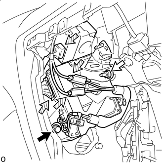

Bolt 
Nut 
Connector Remove the bolt and nut.
-
Disconnect the 4 connectors and remove the telephone transceiver assembly with double lock door control relay assembly.
-
-
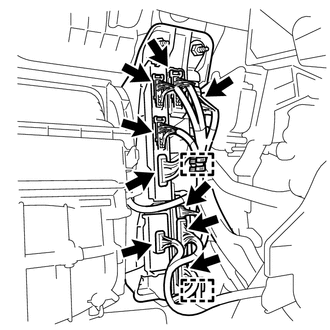
REMOVE ECU INTEGRATION BOX RH (for LHD)
-
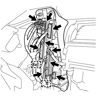
Disconnect the 9 connectors.
-
Detach the 2 clamps.
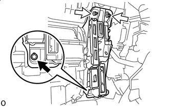
-
Bolt Nut Remove the 2 nuts, bolt and ECU integration box RH.
-
-
REMOVE ECU INTEGRATION BOX LH (for RHD)
-
Disconnect the 9 connectors.
-
Detach the 2 clamps.
-
Bolt Nut Remove the 2 nuts, bolt and ECU integration box LH.
-
-
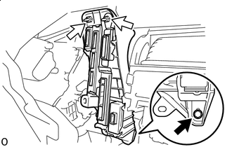
REMOVE NETWORK GATEWAY ECU
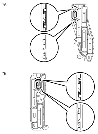
*A for LHD *B for RHD
-
Detach the 2 claws and remove the network gateway ECU.
-