CAN COMMUNICATION SYSTEM(w/o Central Gateway ECU) Open in CAN Main Wire
DESCRIPTION
There may be an open circuit between the CAN bus lines when the resistance between terminals 6 (CANH) and 14 (CANL) of the DLC3 is 70 Ω or higher.
| Symptom | Trouble Area |
|---|---|
| The resistance between terminals 6 (CANH) and 14 (CANL) of the DLC3 is 70 Ω or higher. |
|
*2: for RHD
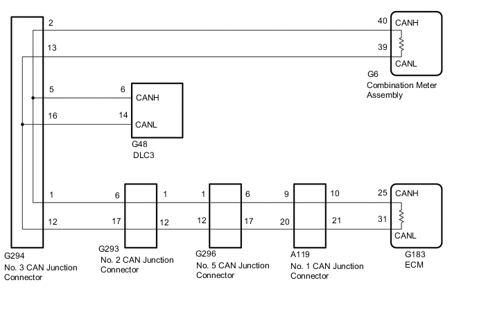
WIRING DIAGRAM
-
for LHD
-
for RHD
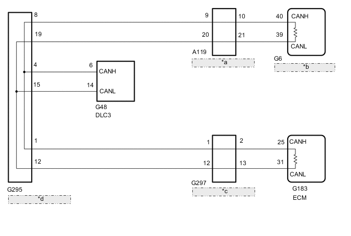
*a No. 1 CAN Junction Connector *b Combination Meter Assembly *c No. 6 CAN Junction Connector *d No. 4 CAN Junction Connector
CAUTION / NOTICE / HINT
CAUTION:
When performing the confirmation driving pattern, obey all speed limits and traffic laws.
Note
-
Because the order of diagnosis is important to allow correct diagnosis, make sure to begin troubleshooting using How to Proceed with Troubleshooting when CAN communication system related DTCs are output.
-
Before measuring the resistance of the CAN bus, turn the ignition switch off and leave the vehicle for 1 minute or more without operating the key or any switches, or opening or closing the doors. After that, disconnect the cable from the negative (-) battery terminal and leave the vehicle for 1 minute or more before measuring the resistance.
-
After turning the ignition switch off, waiting time may be required before disconnecting the cable from the negative (-) battery terminal. Therefore, make sure to read the disconnecting the cable from the negative (-) battery terminal notices before proceeding with work.
-
Some parts must be initialized and set when replacing or removing and installing parts.
-
After performing repairs, perform the DTC check procedure and confirm that the DTCs are not output again.
DTC check procedure: Turn the ignition switch to ON and wait for 1 minute or more. Then operate the suspected malfunctioning system and drive the vehicle at 60 km/h (37 mph) or more for 5 minutes or more.
-
After the repair, perform the CAN bus check and check that all the ECUs and sensors connected to the CAN communication system are displayed as normal.
-
When replacing the combination meter assembly, always replace it with a new one. If a combination meter assembly which was installed to another vehicle is used, the information stored in it will not match the information from the vehicle and a DTC may be stored.
Tech Tips
-
Before disconnecting related connectors for inspection, push in on each connector body to check that the connector is not loose or disconnected.
-
When a connector is disconnected, check that the terminals and connector body are not cracked, deformed or corroded.
PROCEDURE
-
CHECK FOR OPEN IN CAN BUS WIRE (DLC3 CAN BRANCH WIRE)
-
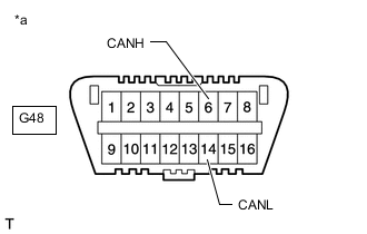
*a Front view of DLC3 Disconnect the cable from the negative (-) battery terminal.
-
Measure the resistance according to the value(s) in the table below.
Standard Resistance Tester Connection Condition Specified Condition G48-6 (CANH) - G48-14 (CANL) Cable disconnected from negative (-) battery terminal 108 to 132 Ω Note
When the measured value is 133 Ω or higher and a CAN communication system DTC is output, there may be a fault besides disconnection of the DLC3 branch line. For that reason, troubleshooting should be performed again from How to Proceed with Troubleshooting after repairing the trouble area.
Result Result Proceed to OK (for LHD) A OK (for RHD) B NG C
B 
CHECK FOR OPEN IN CAN BUS WIRE (NO. 4 CAN JUNCTION CONNECTOR) Click here
C 
REPAIR OR REPLACE CAN BRANCH WIRE CONNECTED TO DLC3 (CANH, CANL)
A 
-
-
CHECK FOR OPEN IN CAN BUS WIRE (NO. 2 CAN JUNCTION CONNECTOR)
-
Disconnect the No. 2 CAN junction connector.
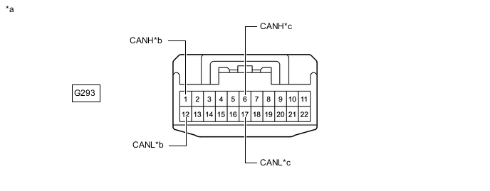
*a Front view of wire harness connector
(to No. 2 CAN Junction Connector)
*b to No. 5 CAN Junction Connector *c to No. 3 CAN Junction Connector - - -
Measure the resistance according to the value(s) in the table below.
Standard Resistance Tester Connection Condition Specified Condition Connected to G293-1 (CANH) - G293-12 (CANL) Cable disconnected from negative (-) battery terminal 108 to 132 Ω No. 5 CAN junction connector G293-6 (CANH) - G293-17 (CANL) Cable disconnected from negative (-) battery terminal 108 to 132 Ω No. 3 CAN junction connector Result Result Proceed to OK A NG (No. 3 CAN junction connector CAN main wire) B NG (No. 5 CAN junction connector CAN main wire) C
A
REPLACE NO. 2 CAN JUNCTION CONNECTOR
C
CONNECT CONNECTOR Click here
B
-
-
CONNECT CONNECTOR
-
Reconnect the G293 No. 2 CAN junction connector.
Result Proceed to NEXT
NEXT
-
-
CHECK FOR OPEN IN CAN BUS WIRE (NO. 3 CAN JUNCTION CONNECTOR)
-
Disconnect the No. 3 CAN junction connector.
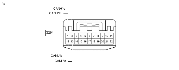
*a Front view of wire harness connector
(to No. 3 CAN Junction Connector)
*b to No. 2 CAN Junction Connector *c to Combination Meter Assembly - - -
Measure the resistance according to the value(s) in the table below.
Standard Resistance Tester Connection Condition Specified Condition Connected to G294-1 (CANH) - G294-12 (CANL) Cable disconnected from negative (-) battery terminal 108 to 132 Ω No. 2 CAN junction connector G294-2 (CANH) - G294-13 (CANL) Cable disconnected from negative (-) battery terminal 108 to 132 Ω Combination meter assembly Result Result Proceed to OK A NG (Combination meter assembly CAN main wire) B NG (No. 2 CAN junction connector CAN main wire) C
A
REPLACE NO. 3 CAN JUNCTION CONNECTOR
C
REPAIR OR REPLACE CAN MAIN WIRE OR CONNECTOR (NO. 3 CAN JUNCTION CONNECTOR - NO. 2 CAN JUNCTION CONNECTOR)
B
-
-
CONNECT CONNECTOR
-
Reconnect the G294 No. 3 CAN junction connector.
Result Proceed to NEXT
NEXT
-
-
CHECK FOR OPEN IN CAN BUS WIRE (COMBINATION METER ASSEMBLY - NO. 3 CAN JUNCTION CONNECTOR)
-
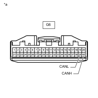
*a Front view of wire harness connector
(to Combination Meter Assembly)
Disconnect the combination meter assembly connector.
-
Measure the resistance according to the value(s) in the table below.
Standard Resistance Tester Connection Condition Specified Condition G6-40 (CANH) - G6-39 (CANL) Cable disconnected from negative (-) battery terminal 108 to 132 Ω Result Proceed to OK NG
OK
REPLACE COMBINATION METER ASSEMBLY Click here
NG
REPAIR OR REPLACE CAN MAIN WIRE OR CONNECTOR (COMBINATION METER ASSEMBLY - NO. 3 CAN JUNCTION CONNECTOR)
-
-
CONNECT CONNECTOR
-
Reconnect the G293 No. 2 CAN junction connector.
Result Proceed to NEXT
NEXT
-
-
CHECK FOR OPEN IN CAN BUS WIRE (NO. 5 CAN JUNCTION CONNECTOR)
-
Disconnect the No. 5 CAN junction connector.
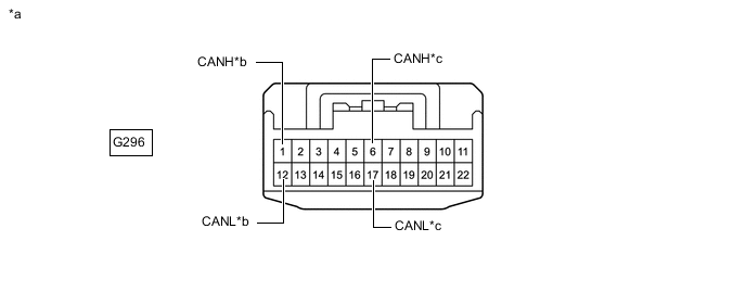
*a Front view of wire harness connector
(to No. 5 CAN Junction Connector)
*b to No. 2 CAN Junction Connector *c to No. 1 CAN Junction Connector - - -
Measure the resistance according to the value(s) in the table below.
Standard Resistance Tester Connection Condition Specified Condition Connected to G296-1 (CANH) - G296-12 (CANL) Cable disconnected from negative (-) battery terminal 108 to 132 Ω No. 2 CAN junction connector G296-6 (CANH) - G296-17 (CANL) Cable disconnected from negative (-) battery terminal 108 to 132 Ω No. 1 CAN junction connector Result Result Proceed to OK A NG (No. 1 CAN junction connector CAN main wire) B NG (No. 2 CAN junction connector CAN main wire) C
A
REPLACE NO. 5 CAN JUNCTION CONNECTOR
C
REPAIR OR REPLACE CAN MAIN WIRE OR CONNECTOR (NO. 5 CAN JUNCTION CONNECTOR - NO. 2 CAN JUNCTION CONNECTOR)
B
-
-
CONNECT CONNECTOR
-
Reconnect the G296 No. 5 CAN junction connector.
Result Proceed to NEXT
NEXT
-
-
CHECK FOR OPEN IN CAN BUS WIRE (NO. 1 CAN JUNCTION CONNECTOR)
-
Disconnect the No. 1 CAN junction connector.

*a Front view of wire harness connector
(to No. 1 CAN Junction Connector)
*b to No. 5 CAN Junction Connector *c to ECM - - -
Measure the resistance according to the value(s) in the table below.
Standard Resistance Tester Connection Condition Specified Condition Connected to A119-9 (CANH) - A119-20 (CANL) Cable disconnected from negative (-) battery terminal 108 to 132 Ω No. 5 CAN junction connector A119-10 (CANH) - A119-21 (CANL) Cable disconnected from negative (-) battery terminal 108 to 132 Ω ECM Result Result Proceed to OK A NG (ECM CAN main wire) B NG (No. 5 CAN junction connector CAN main wire) C
A
REPLACE NO. 1 CAN JUNCTION CONNECTOR
C
REPAIR OR REPLACE CAN MAIN WIRE OR CONNECTOR (NO. 1 CAN JUNCTION CONNECTOR - NO. 5 CAN JUNCTION CONNECTOR)
B
-
-
CONNECT CONNECTOR
-
Reconnect the A119 No. 1 CAN junction connector.
Result Proceed to NEXT
NEXT
-
-
CHECK FOR OPEN IN CAN BUS WIRE (ECM - NO. 1 CAN JUNCTION CONNECTOR)
-
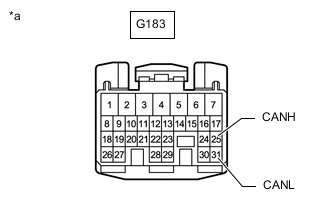
*a Front view of wire harness connector
(to ECM)
Disconnect the ECM connector.
-
Measure the resistance according to the value(s) in the table below.
Standard Resistance Tester Connection Condition Specified Condition G183-25 (CANH) - G183-31 (CANL) Cable disconnected from negative (-) battery terminal 108 to 132 Ω Result Proceed to OK NG
OK
REPLACE ECM Click here
NG
REPAIR OR REPLACE CAN MAIN WIRE OR CONNECTOR (ECM - NO. 1 CAN JUNCTION CONNECTOR)
-
-
CHECK FOR OPEN IN CAN BUS WIRE (NO. 4 CAN JUNCTION CONNECTOR)
-
Disconnect the No. 4 CAN junction connector.
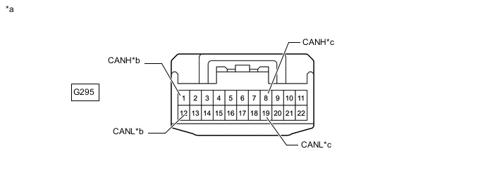
*a Front view of wire harness connector
(to No. 4 CAN Junction Connector)
*b to No. 6 CAN Junction Connector *c to No. 1 CAN Junction Connector - - -
Measure the resistance according to the value(s) in the table below.
Standard Resistance Tester Connection Condition Specified Condition Connected to G295-1 (CANH) - G295-12 (CANL) Cable disconnected from negative (-) battery terminal 108 to 132 Ω No. 6 CAN junction connector G295-8 (CANH) - G295-19 (CANL) Cable disconnected from negative (-) battery terminal 108 to 132 Ω No. 1 CAN junction connector Result Result Proceed to OK A NG (No. 1 CAN junction connector CAN main wire) B NG (No. 6 CAN junction connector CAN main wire) C
A
REPLACE NO. 4 CAN JUNCTION CONNECTOR
C
CONNECT CONNECTOR Click here
B
-
-
CONNECT CONNECTOR
-
Reconnect the G295 No. 4 CAN junction connector.
Result Proceed to NEXT
NEXT
-
-
CHECK FOR OPEN IN CAN BUS WIRE (NO. 1 CAN JUNCTION CONNECTOR)
-
Disconnect the No. 1 CAN junction connector.
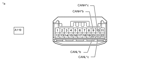
*a Front view of wire harness connector
(to No. 1 CAN Junction Connector)
*b to No. 4 CAN Junction Connector *c to Combination Meter Assembly - - -
Measure the resistance according to the value(s) in the table below.
Standard Resistance Tester Connection Condition Specified Condition Connected to A119-9 (CANH) - A119-20 (CANL) Cable disconnected from negative (-) battery terminal 108 to 132 Ω No. 4 CAN junction connector A119-10 (CANH) - A119-21 (CANL) Cable disconnected from negative (-) battery terminal 108 to 132 Ω Combination meter assembly Result Result Proceed to OK A NG (Combination meter assembly CAN main wire) B NG (No. 4 CAN junction connector CAN main wire) C
A
REPLACE NO. 1 CAN JUNCTION CONNECTOR
C
REPAIR OR REPLACE CAN MAIN WIRE OR CONNECTOR (NO. 1 CAN JUNCTION CONNECTOR - NO. 4 CAN JUNCTION CONNECTOR)
B
-
-
CONNECT CONNECTOR
-
Reconnect the A119 No. 1 CAN junction connector.
Result Proceed to NEXT
NEXT
-
-
CHECK FOR OPEN IN CAN BUS WIRE (COMBINATION METER ASSEMBLY - NO. 1 CAN JUNCTION CONNECTOR)
-
*a Front view of wire harness connector
(to Combination Meter Assembly)
Disconnect the combination meter assembly connector.
-
Measure the resistance according to the value(s) in the table below.
Standard Resistance Tester Connection Condition Specified Condition G6-40 (CANH) - G6-39 (CANL) Cable disconnected from negative (-) battery terminal 108 to 132 Ω Result Proceed to OK NG
OK
REPLACE COMBINATION METER ASSEMBLY Click here
NG
REPAIR OR REPLACE CAN MAIN WIRE OR CONNECTOR (COMBINATION METER ASSEMBLY - NO. 1 CAN JUNCTION CONNECTOR)
-
-
CONNECT CONNECTOR
-
Reconnect the G295 No. 4 CAN junction connector.
Result Proceed to NEXT
NEXT
-
-
CHECK FOR OPEN IN CAN BUS WIRE (NO. 6 CAN JUNCTION CONNECTOR)
-
Disconnect the No. 6 CAN junction connector.

*a Front view of wire harness connector
(to No. 6 CAN Junction Connector)
*b to No. 4 CAN Junction Connector *c to ECM - - -
Measure the resistance according to the value(s) in the table below.
Standard Resistance Tester Connection Condition Specified Condition Connected to G297-1 (CANH) - G297-12 (CANL) Cable disconnected from negative (-) battery terminal 108 to 132 Ω No. 4 CAN junction connector G297-2 (CANH) - G297-13 (CANL) Cable disconnected from negative (-) battery terminal 108 to 132 Ω ECM Result Result Proceed to OK A NG (ECM CAN main wire) B NG (No. 4 CAN junction connector CAN main wire) C
A
REPLACE NO. 6 CAN JUNCTION CONNECTOR
C
REPAIR OR REPLACE CAN MAIN WIRE OR CONNECTOR (NO. 6 CAN JUNCTION CONNECTOR - NO. 4 CAN JUNCTION CONNECTOR)
B
-
-
CONNECT CONNECTOR
-
Reconnect the G297 No. 6 CAN junction connector.
Result Proceed to NEXT
NEXT
-
-
CHECK FOR OPEN IN CAN BUS WIRE (ECM - NO. 6 CAN JUNCTION CONNECTOR)
-
*a Front view of wire harness connector
(to ECM)
Disconnect the ECM connector.
-
Measure the resistance according to the value(s) in the table below.
Standard Resistance Tester Connection Condition Specified Condition G183-25 (CANH) - G183-31 (CANL) Cable disconnected from negative (-) battery terminal 108 to 132 Ω Result Proceed to OK NG
OK
REPLACE ECM Click here
NG
REPAIR OR REPLACE CAN MAIN WIRE OR CONNECTOR (ECM - NO. 6 CAN JUNCTION CONNECTOR)
-