CAN COMMUNICATION SYSTEM(w/o Central Gateway ECU) TERMINALS OF ECU
Note
-
After turning the ignition switch off, waiting time may be required before disconnecting the cable from the negative (-) battery terminal. Therefore, make sure to read the disconnecting the cable from the negative (-) battery terminal notices before proceeding with work.
-
Before measuring the resistance of the CAN bus, turn the ignition switch off and leave the vehicle for 1 minute or more without operating the key or any switches, or opening or closing the doors. After that, disconnect the cable from the negative (-) battery terminal and leave the vehicle for 1 minute or more before measuring the resistance.
-
This section describes the standard values for all CAN related components.
Tech Tips
-
The systems (ECUs and sensors) that use CAN communication vary depending on the vehicle and optional equipment. Check which systems (ECUs and sensors) are installed to the vehicle.
-
Operating the ignition switch, any other switches or a door triggers related ECU and sensor communication on the CAN. This communication will cause the resistance value to change.
-
Even after DTCs are cleared, if a DTC is stored again after driving the vehicle for a while, the malfunction may be occurring due to vibration of the vehicle. In such a case, wiggling the ECUs or wire harness while performing the inspection below may help determine the cause of the malfunction.
-
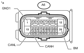
NO. 1 CAN JUNCTION CONNECTOR
-
Check the No. 1 CAN junction connector.
-
Connection diagram
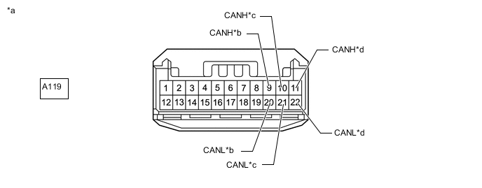
*a Front view of wire harness connector
(to No. 1 CAN Junction Connector)
*b
-
for No. 5 CAN Junction Connector (for LHD)
-
for No. 4 CAN Junction Connector (for RHD)
*c
-
for ECM (for LHD)
-
for Combination Meter Assembly (for RHD)
*d for Brake Actuator Assembly (Skid Control ECU) -
-
Check the connection diagram of the components which are connected to the No. 1 CAN junction connector.
Terminal No. (Symbol) Wiring Color Connected to A119-9 (CANH) R*1, B*2
-
No. 5 CAN junction connector*1
-
No. 4 CAN junction connector*2
A119-20 (CANL) W A119-10 (CANH) LG
-
ECM*1
-
Combination meter assembly*2
A119-21 (CANL) W A119-11 (CANH) B*1, R*2 Brake actuator assembly (skid control ECU) A119-22 (CANL) W *1: for LHD
*2: for RHD
-
-
-
-
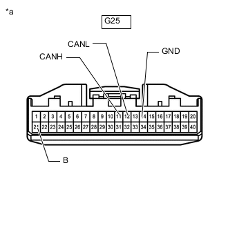
NO. 2 CAN JUNCTION CONNECTOR (for LHD)
-
Check the No. 2 CAN junction connector.
-
Connection diagram
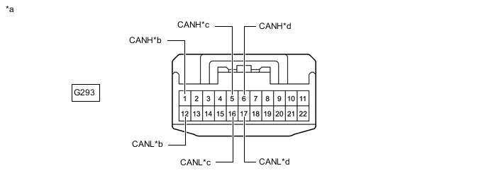
*a Front view of wire harness connector
(to No. 2 CAN Junction Connector)
*b for No. 5 CAN Junction Connector *c for Airbag Sensor Assembly *d for No. 3 CAN Junction Connector -
Check the connection diagram of the components which are connected to the No. 2 CAN junction connector.
Terminal No. (Symbol) Wiring Color Connected to G293-1 (CANH) GR No. 5 CAN junction connector G293-12 (CANL) W G293-5 (CANH) Y Airbag sensor assembly G293-16 (CANL) W G293-6 (CANH) LG No. 3 CAN junction connector G293-17 (CANL) W
-
-
-
NO. 3 CAN JUNCTION CONNECTOR (for LHD)
-
Check the No. 3 CAN junction connector.
-
Connection diagram
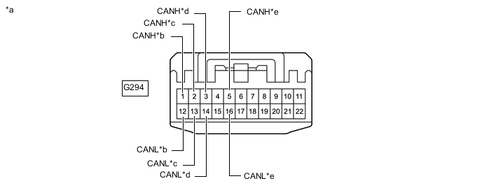
*a Front view of wire harness connector
(to No. 3 CAN Junction Connector)
*b for No. 2 CAN Junction Connector *c for Combination Meter Assembly *d for Main Body ECU (Multiplex Network Body ECU) *e for DLC3 - - -
Check the connection diagram of the components which are connected to the No. 3 CAN junction connector.
Terminal No. Wiring Color Connected to G294-1 (CANH) LG No. 2 CAN junction connector G294-12 (CANL) W G294-2 (CANH) V Combination meter assembly G294-13 (CANL) W G294-3 (CANH) L Main body ECU (multiplex network body ECU) G294-14 (CANL) W G294-5 (CANH) R DLC3 G294-16 (CANL) W
-
-
-
NO. 4 CAN JUNCTION CONNECTOR (for RHD)
-
Check the No. 4 CAN junction connector.
-
Connection diagram
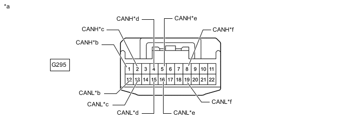
*a Front view of wire harness connector
(to No. 4 CAN Junction Connector)
*b for No. 6 CAN Junction Connector *c for Main Body ECU (Multiplex Network Body ECU) *d for DLC3 *e for Airbag Sensor Assembly *f for No. 1 CAN Junction Connector -
Check the connection diagram of the components which are connected to the No. 4 CAN junction connector.
Terminal No. (Symbol) Wiring Color Connected to G295-1 (CANH) GR No. 6 CAN junction connector G295-12 (CANL) W G295-2 (CANH) L Main body ECU (multiplex network body ECU) G295-13 (CANL) W G295-4 (CANH) R DLC3 G295-15 (CANL) W G295-5 (CANH) P Airbag sensor assembly G295-16 (CANL) W G295-8 (CANH) B No. 1 CAN junction connector G295-19 (CANL) W
-
-
-
NO. 5 CAN JUNCTION CONNECTOR (for LHD)
-
Check the No. 5 CAN junction connector.
-
Connection diagram
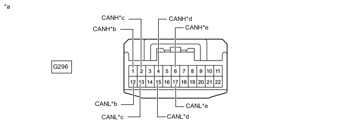
*a Front view of wire harness connector
(to No. 5 CAN Junction Connector)
*b for No. 2 CAN Junction Connector *c for 4 Wheel Drive Control ECU *d for Air Conditioning Amplifier Assembly *e for No. 1 CAN Junction Connector - - -
Check the connection diagram of the components which are connected to the No. 5 CAN junction connector.
Terminal No. (Symbol) Wiring Color Connected to G296-1 (CANH) GR No. 2 CAN junction connector G296-12 (CANL) W G296-2 (CANH) G 4 wheel drive control ECU G296-13 (CANL) W G296-4 (CANH) BR Air conditioning amplifier assembly G296-15 (CANL) W G296-6 (CANH) R No. 1 CAN junction connector G296-17 (CANL) W
-
-
-
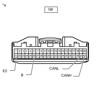
NO. 6 CAN JUNCTION CONNECTOR (for RHD)
-
Check the No. 6 CAN junction connector.
-
Connection diagram
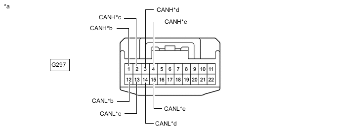
*a Front view of wire harness connector
(to No. 6 CAN Junction Connector)
*b for No. 4 CAN Junction Connector *c for ECM *d for 4 Wheel Drive Control ECU *e for Air Conditioning Amplifier Assembly - - -
Check the connection diagram of the components which are connected to the No. 6 CAN junction connector.
Terminal No. (Symbol) Wiring Color Connected to G297-1 (CANH) GR No. 4 CAN junction connector G297-12 (CANL) W G297-2 (CANH) LG ECM G297-13 (CANL) W G297-3 (CANH) G 4 wheel drive control ECU G297-14 (CANL) W G297-4 (CANH) BR Air conditioning amplifier assembly G297-15 (CANL) W
-
-
-
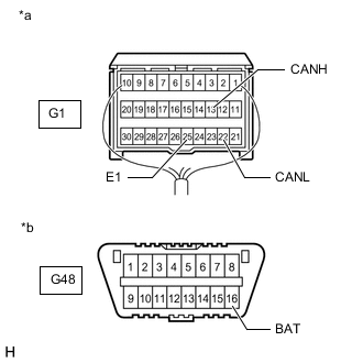
DLC3
-
Disconnect the cable from the negative (-) battery terminal.
-
Measure the resistance according to the value(s) in the table below.
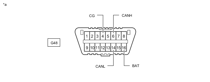
*a Front view of DLC3 - -
-
-
ECM
Refer to Terminals of ECU.
-
Disconnect the cable from the negative (-) battery terminal.
-
Disconnect the ECM connector.
*a Front view of wire harness connector
(to ECM)
- - -
Measure the resistance according to the value(s) in the table below.
-
-
BRAKE ACTUATOR ASSEMBLY (SKID CONTROL ECU)
Refer to Terminals of ECU.
-
*a Front view of wire harness connector
(to Brake Actuator Assembly [Skid Control ECU])
Disconnect the brake actuator assembly (skid control ECU) connector.
-
Measure the resistance according to the value(s) in the table below.
-
-
AIR CONDITIONING AMPLIFIER ASSEMBLY
Refer to Terminals of ECU.
-
Disconnect the cable from the negative (-) battery terminal.
-
*a Front view of wire harness connector
(to Air Conditioning Amplifier Assembly)
Disconnect the air conditioning amplifier assembly connector.
-
Measure the resistance according to the value(s) in the table below.
-
-
AIRBAG SENSOR ASSEMBLY
Refer to Terminals of ECU.
-
Disconnect the cable from the negative (-) battery terminal, and wait for at least 90 seconds.
-
*a Rear view of wire harness connector
(to Airbag Sensor Assembly)
*b Front view of DLC3 Disconnect the airbag sensor assembly connector.
Note
When disconnecting the cable, some systems need to be initialized after the cable is reconnected.
-
Measure the resistance according to the value(s) in the table below.
-
-
COMBINATION METER ASSEMBLY
Refer to Terminals of ECU.
-
Disconnect the cable from the negative (-) battery terminal.
-
*a Front view of wire harness connector
(to Combination Meter Assembly)
Disconnect the combination meter assembly connector.
-
Measure the resistance according to the value(s) in the table below.
-
-
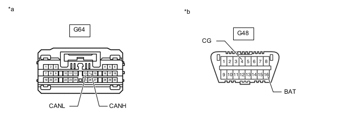
4 WHEEL DRIVE CONTROL ECU
Refer to Terminals of ECU.
-
Disconnect the cable from the negative (-) battery terminal.
-
Disconnect the 4 wheel drive control ECU connectors.
*a Front view of wire harness connector
(to 4 Wheel Drive Control ECU)
- - -
Measure the resistance according to the value(s) in the table below.
-
-
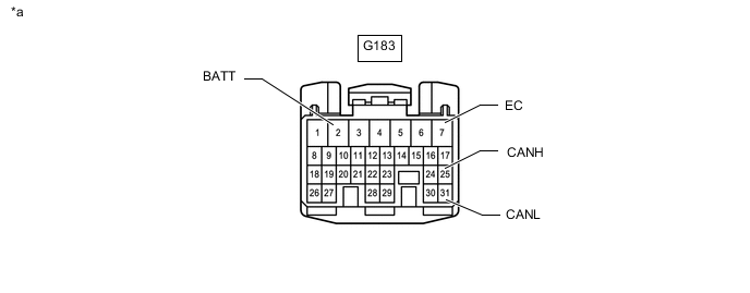
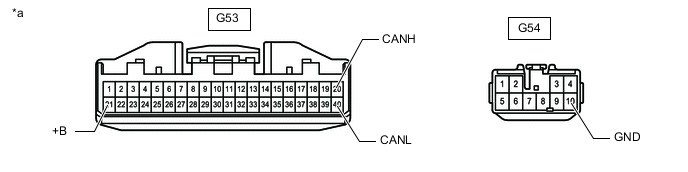
MAIN BODY ECU (MULTIPLEX NETWORK BODY ECU)
Refer to Terminals of ECU.
-
Disconnect the cable from the negative (-) battery terminal.
-
Disconnect the main body ECU (multiplex network body ECU) connector.
*a Front view of wire harness connector
(to Main Body ECU [Multiplex Network Body ECU])
*b Front view of DLC3 -
Measure the resistance according to the value(s) in the table below.
-