CAN COMMUNICATION SYSTEM(w/ Central Gateway ECU) Check Bus 5 Lines for Short Circuit
DESCRIPTION
There may be a short circuit between the CAN main bus lines and/or CAN branch lines when the resistance between terminals 15 (CA5H) and 16 (CA5L) of the central gateway ECU (network gateway ECU) is below 54 Ω.
| Symptom | Trouble Area |
|---|---|
| Resistance between terminals 15 (CA5H) and 16 (CA5L) of the central gateway ECU (network gateway ECU) is below 54 Ω. |
|
*2: w/ Pre-crash Safety System
*3: w/ TOYOTA Parking Assist-sensor System (w/ Multi-display)
*4: w/ Kinetic Dynamic Suspension System
*5: w/ Pre-crash Safety System
*6: w/ Blind Spot Monitor System
*7: w/ Air Suspension System
WIRING DIAGRAM
-
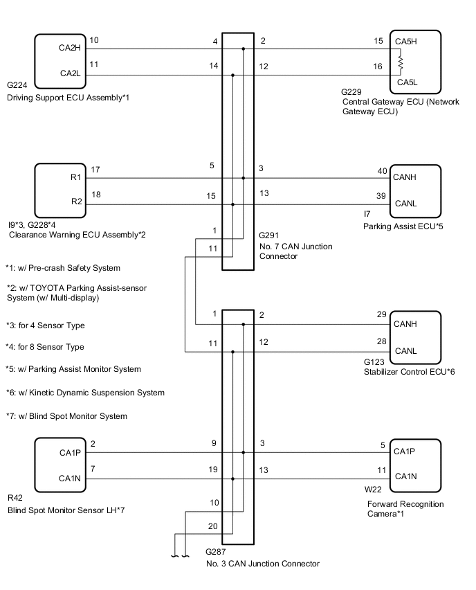
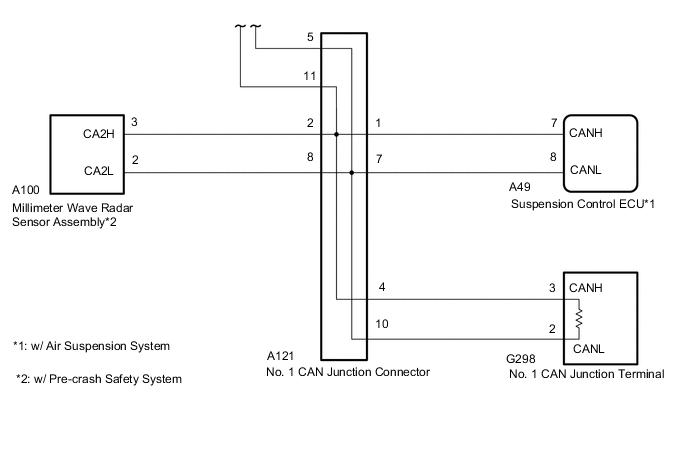
for LHD:
-
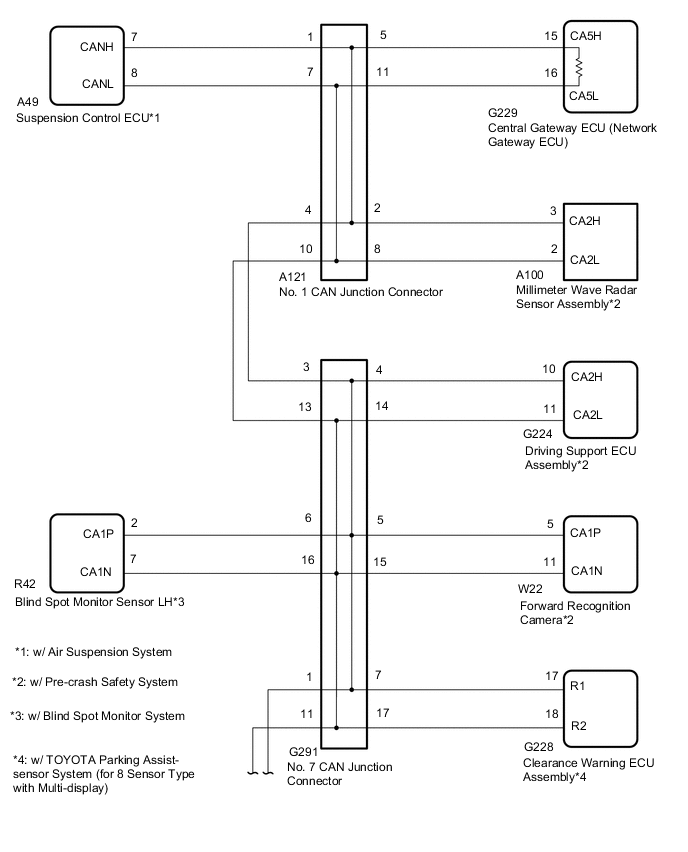
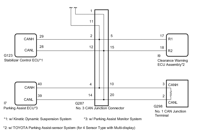
for RHD:
CAUTION / NOTICE / HINT
CAUTION:
When performing the confirmation driving pattern, obey all speed limits and traffic laws.
Note
-
Because the order of diagnosis is important to allow correct diagnosis, make sure to begin troubleshooting using How to Proceed with Troubleshooting when CAN communication system related DTCs are output.
-
Before measuring the resistance of the CAN bus, turn the ignition switch off and leave the vehicle for 1 minute or more without operating the key or any switches, or opening or closing the doors. After that, disconnect the cable from the negative (-) battery terminal and leave the vehicle for 1 minute or more before measuring the resistance.
-
After turning the ignition switch off, waiting time may be required before disconnecting the cable from the negative (-) battery terminal. Therefore, make sure to read the disconnecting the cable from the negative (-) battery terminal notices before proceeding with work.
-
Some parts must be initialized and set when replacing or removing and installing parts.
-
After performing repairs, perform the DTC check procedure and confirm that the DTCs are not output again.
DTC check procedure: Turn the ignition switch to ON and wait for 1 minute or more. Then operate the suspected malfunctioning system and drive the vehicle at 60 km/h (37 mph) or more for 5 minutes or more.
-
After the repair, perform the CAN bus check and check that all the ECUs and sensors connected to the CAN communication system are displayed as normal.
Tech Tips
-
Before disconnecting related connectors for inspection, push in on each connector body to check that the connector is not loose or disconnected.
-
When a connector is disconnected, check that the terminals and connector body are not cracked, deformed or corroded.
PROCEDURE
-
CHECK VEHICLE TYPE
-
Check vehicle type.
Result Result Proceed to for LHD A for RHD B
B 
CHECK FOR SHORT IN CAN BUS WIRES (NO. 7 CAN JUNCTION CONNECTOR) Click here
A 
-
-
CHECK FOR SHORT IN CAN BUS WIRES (NO. 3 CAN JUNCTION CONNECTOR)
-
Disconnect the cable from the negative (-) battery terminal.
-
Disconnect the No. 3 CAN junction connector.
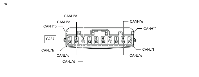
*a Front view of wire harness connector
(to No. 3 CAN Junction Connector)
*b to No. 7 CAN Junction Connector *c to Stabilizer Control ECU (w/ Kinetic Dynamic Suspension System) *d to Forward Recognition Camera (w/ Pre-crash Safety System) *e to Blind Spot Monitor Sensor LH (w/ Blind Spot Monitor System) *f to No. 1 CAN Junction Connector -
Measure the resistance according to the value(s) in the table below.
Standard Resistance *1: w/ Kinetic Dynamic Suspension SystemTester Connection Condition Specified Condition Connected to G287-1 (CANH) - G287-11 (CANL) Cable disconnected from negative (-) battery terminal 108 to 132 Ω No. 7 CAN junction connector G287-2 (CANH) - G287-12 (CANL) Cable disconnected from negative (-) battery terminal 200 Ω or higher Stabilizer control ECU*1 G287-3 (CANH) - G287-13 (CANL) Cable disconnected from negative (-) battery terminal 200 Ω or higher Forward recognition camera*2 G287-9 (CANH) - G287-19 (CANL) Cable disconnected from negative (-) battery terminal 200 Ω or higher Blind spot monitor sensor LH*3 G287-10 (CANH) - G287-20 (CANL) Cable disconnected from negative (-) battery terminal 108 to 132 Ω No. 1 CAN junction connector
*2: w/ Pre-crash Safety System
*3: w/ Blind Spot Monitor System
Result Result Proceed to OK A NG (No. 1 CAN junction connector CAN main wire) B NG (No. 7 CAN junction connector CAN main wire) C NG (Wire to ECU or sensor) D
A 
REPLACE NO. 3 CAN JUNCTION CONNECTOR
C
CONNECT CONNECTOR Click here
D
GO TO STEP 20 Click here
B
-
-
CONNECT CONNECTOR
-
Reconnect the G287 No. 3 CAN junction connector.
Result Proceed to NEXT
NEXT
-
-
CHECK FOR SHORT IN CAN BUS WIRES (NO. 1 CAN JUNCTION CONNECTOR)
-

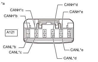
*a Front view of wire harness connector
(to No. 1 CAN Junction Connector)
*b to Suspension Control ECU (w/ Air Suspension System) *c to Millimeter Wave Radar Sensor Assembly (w/ Pre-crash Safety System) *d to No. 1 CAN Junction Terminal *e to No. 3 CAN Junction Connector Disconnect the No. 1 CAN junction connector.
-
Measure the resistance according to the value(s) in the table below.
Standard Resistance *1: w/ Air Suspension SystemTester Connection Condition Specified Condition Connected to A121-1 (CANH) - A121-7 (CANL) Cable disconnected from negative (-) battery terminal 200 Ω or higher Suspension control ECU*1 A121-2 (CANH) - A121-8 (CANL) Cable disconnected from negative (-) battery terminal 200 Ω or higher Millimeter wave radar sensor assembly*2 A121-4 (CANH) - A121-10 (CANL) Cable disconnected from negative (-) battery terminal 108 to 132 Ω No. 1 CAN junction terminal A121-5 (CANH) - A121-11 (CANL) Cable disconnected from negative (-) battery terminal 108 to 132 Ω No. 3 CAN junction connector
*2: w/ Pre-crash Safety System
Result Result Proceed to OK A NG (No. 1 CAN junction terminal CAN main wire) B NG (No. 3 CAN junction connector CAN main wire) C NG (Wire to ECU or sensor) D
A
REPLACE NO. 1 CAN JUNCTION CONNECTOR
C
REPAIR OR REPLACE CAN BUS MAIN WIRE OR CONNECTOR (NO. 1 CAN JUNCTION CONNECTOR- NO. 3 CAN JUNCTION CONNECTOR)
D
GO TO STEP 20 Click here
B
-
-
CONNECT CONNECTOR
-
Reconnect the A121 No. 1 CAN junction connector.
Result Proceed to NEXT
NEXT
-
-
CHECK SHORT IN CAN BUS WIRES (NO. 1 CAN JUNCTION TERMINAL - NO. 1 CAN JUNCTION CONNECTOR)
-
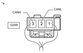
*a Rear view of wire harness connector
(to No. 1 CAN Junction Terminal)
Disconnect the No. 1 CAN junction terminal connector.
-
Measure the resistance according to the value(s) in the table below.
Standard Resistance Tester Connection Condition Specified Condition G298-3 (CANH) - G298-2 (CANL) Cable disconnected from negative (-) battery terminal 108 to 132 Ω Result Proceed to OK NG
OK
REPLACE NO. 1 CAN JUNCTION TERMINAL
NG
REPAIR OR REPLACE CAN BUS MAIN WIRE OR CONNECTOR (NO. 1 CAN JUNCTION TERMINAL - NO. 1 CAN JUNCTION CONNECTOR)
-
-
CONNECT CONNECTOR
-
Reconnect the G287 No. 3 CAN junction connector.
Result Proceed to NEXT
NEXT
-
-
CHECK FOR SHORT IN CAN BUS WIRES (NO. 7 CAN JUNCTION CONNECTOR)
-
Disconnect the No. 7 CAN junction connector.
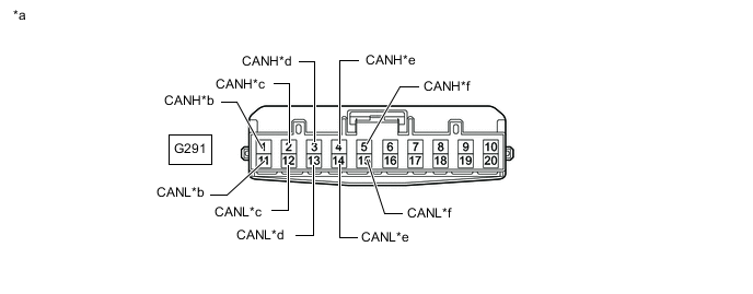
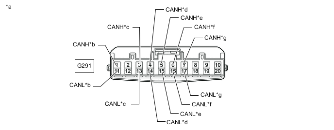
*a Front view of wire harness connector
(to No. 7 CAN Junction Connector)
*b to No. 3 CAN Junction Connector *c to Central Gateway ECU (Network Gateway ECU) *d to Parking Assist ECU (w/ Parking Assist Monitor System) *e to Driving Support ECU Assembly (w/ Pre-crash Safety System) *f to Clearance Warning ECU Assembly (w/ TOYOTA Parking Assist-sensor System [w/ Multi-display]) -
Measure the resistance according to the value(s) in the table below.
Standard Resistance *1: w/ Parking Assist Monitor SystemTester Connection Condition Specified Condition Connected to G291-1 (CANH) - G291-11 (CANL) Cable disconnected from negative (-) battery terminal 108 to 132 Ω No. 3 CAN junction connector G291-2 (CANH) - G291-12 (CANL) Cable disconnected from negative (-) battery terminal 108 to 132 Ω Central gateway ECU (network gateway ECU) G291-3 (CANH) - G291-13 (CANL) Cable disconnected from negative (-) battery terminal 200 Ω or higher Parking assist ECU*1 G291-4 (CANH) - G291-14 (CANL) Cable disconnected from negative (-) battery terminal 200 Ω or higher Driving support ECU assembly*2 G291-5 (CANH) - G291-15 (CANL) Cable disconnected from negative (-) battery terminal 200 Ω or higher Clearance warning ECU assembly*3
*2: w/ Pre-crash Safety System
*3: w/ TOYOTA Parking Assist-sensor System (w/ Multi-display)
Result Result Proceed to OK A NG (Central gateway ECU [network gateway ECU] CAN main wire) B NG (No. 3 CAN junction connector CAN main wire) C NG (Wire to ECU or sensor) D
A
REPLACE NO. 7 CAN JUNCTION CONNECTOR
C
REPAIR OR REPLACE CAN BUS MAIN WIRE OR CONNECTOR (NO. 7 CAN JUNCTION CONNECTOR- NO. 3 CAN JUNCTION CONNECTOR)
D
GO TO STEP 20 Click here
B
-
-
CONNECT CONNECTOR
-
Reconnect the G291 No. 7 CAN junction connector.
Result Proceed to NEXT
NEXT
-
-
CHECK FOR SHORT IN CAN BUS WIRES (CENTRAL GATEWAY ECU [NETWORK GATEWAY ECU] - NO. 7 CAN JUNCTION CONNECTOR)
-
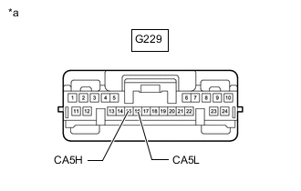
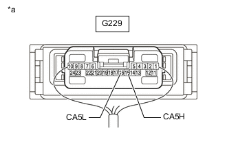
*a Front view of wire harness connector
(to Central Gateway ECU [Network Gateway ECU])
Disconnect the central gateway ECU (network gateway ECU) connector.
-
Measure the resistance according to the value(s) in the table below.
Standard Resistance Tester Connection Condition Specified Condition G229-15 (CA5H) - G229-16 (CA5L) Cable disconnected from negative (-) battery terminal 108 to 132 Ω Result Proceed to OK NG
OK
REPLACE CENTRAL GATEWAY ECU (NETWORK GATEWAY ECU) Click here
NG
REPAIR OR REPLACE CAN BUS MAIN WIRE OR CONNECTOR (CENTRAL GATEWAY ECU [NETWORK GATEWAY ECU] - NO. 7 CAN JUNCTION CONNECTOR)
-
-
CHECK FOR SHORT IN CAN BUS WIRES (NO. 7 CAN JUNCTION CONNECTOR)
-
Disconnect the cable from the negative (-) battery terminal.
-
Disconnect the No. 7 CAN junction connector.
*a Front view of wire harness connector
(to No. 7 CAN Junction Connector)
*b to No. 3 CAN Junction Connector *c to No. 1 CAN Junction Connector *d to Driving Support ECU Assembly (w/ Pre-crash Safety System) *e to Forward Recognition Camera (w/ Pre-crash Safety System) *f to Blind Spot Monitor Sensor LH (w/ Blind Spot Monitor System) *g to Clearance Warning ECU Assembly (w/ TOYOTA Parking Assist-sensor System [for 8 Sensor Type with Multi-display]) - - -
Measure the resistance according to the value(s) in the table below.
Standard Resistance *1: w/ Pre-crash Safety SystemTester Connection Condition Specified Condition Connected to G291-1 (CANH) - G291-11 (CANL) Cable disconnected from negative (-) battery terminal 108 to 132 Ω No. 3 CAN junction connector G291-3 (CANH) - G291-13 (CANL) Cable disconnected from negative (-) battery terminal 108 to 132 Ω No. 1 CAN junction connector G291-4 (CANH) - G291-14 (CANL) Cable disconnected from negative (-) battery terminal 200 Ω or higher Driving support ECU assembly*1 G291-5 (CANH) - G291-15 (CANL) Cable disconnected from negative (-) battery terminal 200 Ω or higher Forward recognition camera*1 G291-6 (CANH) - G291-16 (CANL) Cable disconnected from negative (-) battery terminal 200 Ω or higher Blind spot monitor sensor LH*2 G291-7 (CANH) - G291-17 (CANL) Cable disconnected from negative (-) battery terminal 200 Ω or higher Clearance warning ECU assembly*3
*2: w/ Blind Spot Monitor System
*3: w/ TOYOTA Parking Assist-sensor System (for 8 Sensor Type with Multi-display)
Result Result Proceed to OK A NG (No. 1 CAN junction connector CAN main wire) B NG (No. 3 CAN junction connector CAN main wire) C NG (Wire to ECU or sensor) D
A
REPLACE NO. 7 CAN JUNCTION CONNECTOR
C
CONNECT CONNECTOR Click here
D
GO TO STEP 20 Click here
B
-
-
CONNECT CONNECTOR
-
Reconnect the G291 No. 7 CAN junction connector.
Result Proceed to NEXT
NEXT
-
-
CHECK FOR SHORT IN CAN BUS WIRES (NO. 1 CAN JUNCTION CONNECTOR)
-
*a Front view of wire harness connector
(to No. 1 CAN Junction Connector)
*b to Suspension Control ECU (w/ Air Suspension System) *c to Millimeter Wave Radar Sensor Assembly (w/ Pre-crash Safety System) *d to No. 7 CAN Junction Connector *e to Central Gateway ECU (Network Gateway ECU) Disconnect the No. 1 CAN junction connector.
-
Measure the resistance according to the value(s) in the table below.
Standard Resistance *1: w/ Air Suspension SystemTester Connection Condition Specified Condition Connected to A121-1 (CANH) - A121-7 (CANL) Cable disconnected from negative (-) battery terminal 200 Ω or higher Suspension control ECU*1 A121-2 (CANH) - A121-8 (CANL) Cable disconnected from negative (-) battery terminal 200 Ω or higher Millimeter wave radar sensor assembly*2 A121-4 (CANH) - A121-10 (CANL) Cable disconnected from negative (-) battery terminal 108 to 132 Ω No. 7 CAN junction connector A121-5 (CANH) - A121-11 (CANL) Cable disconnected from negative (-) battery terminal 108 to 132 Ω Central gateway ECU (network gateway ECU)
*2: w/ Pre-crash Safety System
Result Result Proceed to OK A NG (Central gateway ECU [network gateway ECU] CAN main wire) B NG (No. 7 CAN junction terminal CAN main wire) C NG (Wire to ECU or sensor) D
A
REPLACE NO. 1 CAN JUNCTION CONNECTOR
C
REPAIR OR REPLACE CAN BUS MAIN WIRE OR CONNECTOR (NO. 1 CAN JUNCTION CONNECTOR- NO. 7 CAN JUNCTION CONNECTOR)
D
GO TO STEP 20 Click here
B
-
-
CONNECT CONNECTOR
-
Reconnect the A121 No. 1 CAN junction connector.
Result Proceed to NEXT
NEXT
-
-
CHECK FOR SHORT IN CAN BUS WIRES (CENTRAL GATEWAY ECU [NETWORK GATEWAY ECU] - NO. 1 CAN JUNCTION CONNECTOR)
-
*a Front view of wire harness connector
(to Central Gateway ECU [Network Gateway ECU])
Disconnect the central gateway ECU (network gateway ECU) connector.
-
Measure the resistance according to the value(s) in the table below.
Standard Resistance Tester Connection Condition Specified Condition G229-15 (CA5H) - G229-16 (CA5L) Cable disconnected from negative (-) battery terminal 108 to 132 Ω Result Proceed to OK NG
OK
REPLACE CENTRAL GATEWAY ECU (NETWORK GATEWAY ECU) Click here
NG
REPAIR OR REPLACE CAN BUS MAIN WIRE OR CONNECTOR (CENTRAL GATEWAY ECU [NETWORK GATEWAY ECU] - NO. 1 CAN JUNCTION CONNECTOR)
-
-
CONNECT CONNECTOR
-
Reconnect the G291 No. 7 CAN junction connector.
Result Proceed to NEXT
NEXT
-
-
CHECK FOR SHORT IN CAN BUS WIRES (NO. 3 CAN JUNCTION CONNECTOR)
-
Disconnect the No. 3 CAN junction connector.
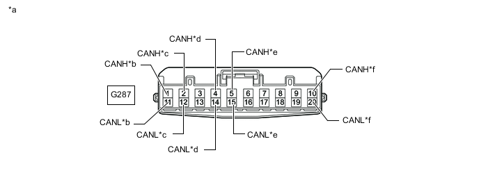
*a Front view of wire harness connector
(to No. 3 CAN Junction Connector)
*b to No. 7 CAN Junction Connector *c to Stabilizer Control ECU (w/ Kinetic Dynamic Suspension System) *d to Parking Assist ECU (w/ Parking Assist Monitor System) *e to Clearance Warning ECU Assembly (w/ TOYOTA Parking Assist-sensor System [for 4 Sensor Type with Multi-display]) *f to No. 1 CAN Junction Terminal -
Measure the resistance according to the value(s) in the table below.
Standard Resistance *1: w/ Kinetic Dynamic Suspension SystemTester Connection Condition Specified Condition Connected to G287-1 (CANH) - G287-11 (CANL) Cable disconnected from negative (-) battery terminal 108 to 132 Ω No. 7 CAN junction connector G287-2 (CANH) - G287-12 (CANL) Cable disconnected from negative (-) battery terminal 200 Ω or higher Stabilizer control ECU*1 G287-4 (CANH) - G287-14 (CANL) Cable disconnected from negative (-) battery terminal 200 Ω or higher Parking assist ECU*2 G287-5 (CANH) - G287-15 (CANL) Cable disconnected from negative (-) battery terminal 200 Ω or higher Clearance warning ECU assembly*3 G287-10 (CANH) - G287-20 (CANL) Cable disconnected from negative (-) battery terminal 108 to 132 Ω No. 1 CAN junction terminal
*2: w/ Parking Assist Monitor System
*3: w/ TOYOTA Parking Assist-sensor System (for 4 Sensor Type with Multi-display)
Result Result Proceed to OK A NG (No. 7 CAN junction connector CAN main wire) B NG (No. 1 CAN junction terminal CAN main wire) C NG (Wire to ECU or sensor) D
A
REPLACE NO. 3 CAN JUNCTION CONNECTOR
B
REPAIR OR REPLACE CAN BUS MAIN WIRE OR CONNECTOR (NO. 3 CAN JUNCTION CONNECTOR- NO. 7 CAN JUNCTION CONNECTOR)
D
CHECK FOR SHORT IN CAN BUS WIRES (ECU, SENSOR) Click here
C
-
-
CONNECT CONNECTOR
-
Reconnect the G287 No. 3 CAN junction connector.
Result Proceed to NEXT
NEXT
-
-
CHECK SHORT IN CAN BUS WIRES (NO. 1 CAN JUNCTION TERMINAL - NO. 3 CAN JUNCTION CONNECTOR)
-
*a Rear view of wire harness connector
(to No. 1 CAN Junction Terminal)
Disconnect the No. 1 CAN junction terminal connector.
-
Measure the resistance according to the value(s) in the table below.
Standard Resistance Tester Connection Condition Specified Condition G298-3 (CANH) - G298-2 (CANL) Cable disconnected from negative (-) battery terminal 108 to 132 Ω Result Proceed to OK NG
OK
REPLACE NO. 1 CAN JUNCTION TERMINAL
NG
REPAIR OR REPLACE CAN BUS MAIN WIRE OR CONNECTOR (NO. 1 CAN JUNCTION TERMINAL - NO. 3 CAN JUNCTION CONNECTOR)
-
-
CHECK FOR SHORT IN CAN BUS WIRES (ECU, SENSOR)
-
Reconnect the wire harness connectors.
-
Disconnect the connector that includes terminals CANH and CANL from the ECU or sensor to which the short circuited branch line is connected.
-
*a Component with harness connected
(Central Gateway ECU [Network Gateway ECU])
Measure the resistance according to the value(s) in the table below.
Standard Resistance Tester Connection Condition Specified Condition G229-15 (CA5H) - G229-16 (CA5L) Cable disconnected from negative (-) battery terminal 54 to 69 Ω Tech Tips
-
If the resistance becomes normal (between 54 and 69 Ω) when the connector is disconnected from the ECU or sensor, there may be a short in the ECU or sensor.
-
If the resistance does not become normal when the connector is disconnected from the ECU or sensor, check for a short in the wire harness and repair or replace the wire harness or connector if necessary.
Result Proceed to OK NG -
OK
REPLACE ECU OR SENSOR
NG
REPLACE CORRESPONDING ECU OR SENSOR
-