POWER DOOR LOCK CONTROL SYSTEM TERMINALS OF ECU
-
CHECK DRIVER SIDE JUNCTION BLOCK ASSEMBLY AND MAIN BODY ECU (MULTIPLEX NETWORK BODY ECU) (for 5L-E)
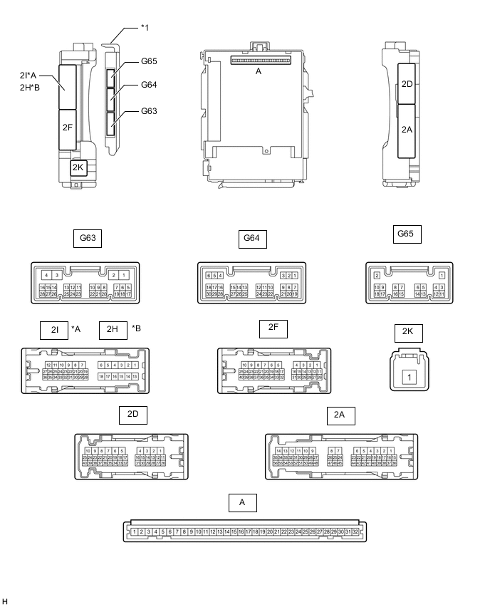
*A for LHD *B for RHD *1 Main Body ECU (Multiplex Network Body ECU) - -
-
Remove the main body ECU (multiplex network body ECU) from the driver side junction block assembly.
-
Connect the driver side junction block assembly connectors.
-
Measure the voltage and resistance according to the value(s) in the table below.
Tester Connection Wiring Color Terminal Description Condition Specified Condition A-30 (BECU) - Body ground - Battery power supply Always 11 to 14 V A-31 (ALTB) - Body ground - Battery power supply Always 11 to 14 V A-32 (IG) - Body ground - Ignition switch power supply Ignition switch ON 11 to 14 V Ignition switch off Below 1 V A-29 (ACC) - Body ground - ACC power supply Ignition switch ACC 11 to 14 V Ignition switch off Below 1 V A-11 (GND1) - Body ground - Ground Always Below 1 Ω -
Install the main body ECU (multiplex network body ECU).
-
Measure the voltage according to the value(s) in the table below.
Tester Connection Wiring Color Terminal Description Condition Specified Condition 2I-27 (FLCY) - Body ground*1 R - Body ground Front door LH courtesy light switch input Front door LH open Below 1 V Front door LH closed 11 to 14 V 2D-31 (FLCY) - Body ground*2 R - Body ground Front door LH courtesy light switch input Front door LH open Below 1 V Front door LH closed 11 to 14 V 2D-15 (FRCY) - Body ground*1 B - Body ground Front door RH courtesy light switch input Front door RH open Below 1 V Front door RH closed 11 to 14 V 2H-26 (FRCY) - Body ground*2 B - Body ground Front door RH courtesy light switch input Front door RH open Below 1 V Front door RH closed 11 to 14 V G65-3 (LCTY) - Body ground V - Body ground Rear door LH courtesy light switch input Rear door LH open Below 1 V Rear door LH closed 11 to 14 V G64-6 (RCTY) - Body ground R - Body ground Rear door RH courtesy light switch input Rear door RH open Below 1 V Rear door RH closed 11 to 14 V G64-19 (BCTY) - Body ground G - Body ground Back door courtesy light switch input Back door open Below 1 V Ignition switch off, all doors closed and back door closed 11 to 14 V G64-11 (L2) - Body ground GR - Body ground Driver side door key-linked lock input Driver side door key cylinder in lock position Below 1 V Ignition switch off, all doors closed and driver side door key cylinder in neutral position 11 to 14 V G64-24 (UL3) - Body ground LG - Body ground Driver side door key-linked unlock input Driver side door key cylinder in unlock position Below 1 V Ignition switch off, all doors closed and driver side door key cylinder in neutral position 11 to 14 V 2D-3 (ACT+) - Body ground L - Body ground Door lock motor lock drive output Driver side door control switch not pushed and driver side door key cylinder in neutral position Below 1 V Lock side of driver side door control switch pushed, or driver side door key cylinder in lock position 11 to 14 V 2I-8 (ACT+) - Body ground*1 L - Body ground Door lock motor lock drive output Driver side door control switch not pushed and driver side door key cylinder in neutral position Below 1 V Lock side of driver side door control switch pushed, or driver side door key cylinder in lock position 11 to 14 V 2H-8 (ACT+) - Body ground*2 L - Body ground Door lock motor lock drive output Driver side door control switch not pushed and driver side door key cylinder in neutral position Below 1 V Lock side of driver side door control switch pushed, or driver side door key cylinder in lock position 11 to 14 V 2D-1 (ACTD) - Body ground G - Body ground Driver side door lock motor unlock drive output Driver side door control switch not pushed and driver side door key cylinder in neutral position Below 1 V Unlock side of driver side door control switch pushed, or driver side door key cylinder in unlock position 11 to 14 V 2D-2 (ACT-) - Body ground W - Body ground Door lock motor unlock drive output Driver side door control switch not pushed and driver side door key cylinder in neutral position Below 1 V Unlock side of driver side door control switch pushed, or driver side door key cylinder in unlock position 11 to 14 V 2I-10 (ACT-) - Body ground*1 W - Body ground Door lock motor unlock drive output Driver side door control switch not pushed and driver side door key cylinder in neutral position Below 1 V Unlock side of driver side door control switch pushed, or driver side door key cylinder in unlock position 11 to 14 V 2H-10 (ACT-) - Body ground*1 W - Body ground Door lock motor unlock drive output Driver side door control switch not pushed and driver side door key cylinder in neutral position Below 1 V Unlock side of driver side door control switch pushed, or driver side door key cylinder in unlock position 11 to 14 V G64-7 (LSFL) - Body ground G - Body ground Front door LH lock position switch input Front door LH unlocked Below 1 V Ignition switch off, all doors closed and front door LH locked 11 to 14 V G64-18 (LSFR) - Body ground G - Body ground Front door RH lock position switch input Front door RH unlocked Below 1 V Ignition switch off, all doors closed and front door RH locked 11 to 14 V 2I-25 (LSWL) - Body ground*1 B - Body ground Rear door LH lock position switch input Rear door LH unlocked Below 1 V Ignition switch off, all doors closed and rear door LH locked 11 to 14 V 2D-16 (LSWL) - Body ground*2 B - Body ground Rear door LH lock position switch input Rear door LH unlocked Below 1 V Ignition switch off, all doors closed and rear door LH locked 11 to 14 V G63-2 (LSWR) - Body ground V - Body ground Rear door RH lock position switch input Rear door RH unlocked Below 1 V Ignition switch off, all doors closed and rear door RH locked 11 to 14 V G65-13 (LSWB) - Body ground SB - Body ground Back door lock position switch input Back door lock unlocked Below 1 V Ignition switch off, all doors closed and back door locked 11 to 14 V 2A-25 (GSW) - Body ground B - Body ground Center airbag sensor signal Ignition switch ON with the center airbag sensor assembly connector disconnected 4.3 to 5.5 V
-
*1: for LHD
-
*2: for RHD
-
-
-
CHECK DRIVER SIDE JUNCTION BLOCK ASSEMBLY AND MAIN BODY ECU (MULTIPLEX NETWORK BODY ECU) (except 5L-E)
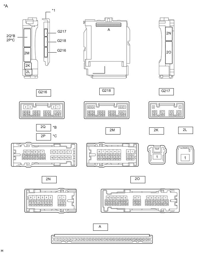
*A Main Body ECU (Multiplex Network Body ECU) with 3 connectors *B for LHD *C for RHD - - *1 Main Body ECU (Multiplex Network Body ECU) - - 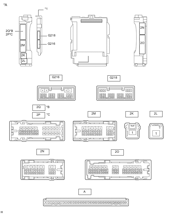
*A Main Body ECU (Multiplex Network Body ECU) with 2 connectors *B for LHD *C for RHD - - *1 Main Body ECU (Multiplex Network Body ECU) - -
-
Remove the main body ECU (multiplex network body ECU) from the driver side junction block assembly.
-
Connect the driver side junction block assembly connectors.
-
Measure the voltage and resistance according to the value(s) in the table below.
Tester Connection Wiring Color Terminal Description Condition Specified Condition A-32 (IG) - Body ground - Ignition power supply Ignition switch ON 11 to 14 V Ignition switch off Below 1 V A-31 (BECU) - Body ground - Battery power supply Always 11 to 14 V A-30 (ACC) - Body ground - ACC power supply Ignition switch ACC 11 to 14 V Ignition switch off Below 1 V A-11 (GND1) - Body ground - Ground Always Below 1 Ω -
Install the main body ECU (multiplex network body ECU).
-
Measure the voltage according to the value(s) in the table below.
Tester Connection Wiring Color Terminal Description Condition Specified Condition G218-6 (FLCY) - Body ground R - Body ground Front door courtesy light switch assembly LH signal Front door LH open Below 1 V Front door LH closed 11 to 14 V G218-27 (FRCY) - Body ground B - Body ground Front door courtesy light switch assembly RH signal Front door RH open Below 1 V Front door RH closed 11 to 14 V 2N-30 (RCTY) - Body ground*1, *3 R - Body ground Rear door courtesy light switch assembly RH signal Rear door RH open Below 1 V Rear door RH closed 11 to 14 V 2P-23 (RCTY) - Body ground*2, *3 R - Body ground Rear door courtesy light switch assembly RH signal Rear door RH open Below 1 V Rear door RH closed 11 to 14 V 2Q-33 (LCTY) - Body ground*1, *3 V - Body ground Rear door courtesy light switch assembly LH signal Rear door LH open Below 1 V Rear door LH closed 11 to 14 V 2O-15 (LCTY) - Body ground*2, *3 V - Body ground Rear door courtesy light switch assembly LH signal Rear door LH open Below 1 V Rear door LH closed 11 to 14 V 2Q-27 (BCTY) - Body ground*1 G - Body ground Back door courtesy light switch assembly signal Back door open Below 1 V Back door close 11 to 14 V 2N-27 (BCTY) - Body ground*2 G - Body ground Back door courtesy light switch assembly signal Back door open Below 1 V Back door close 11 to 14 V G218-29 (L2) - Body ground GR - Body ground Driver side door key-linked lock input Driver side door key cylinder in lock position Below 1 V Ignition switch off, all doors closed and driver side door key cylinder in neutral position 11 to 14 V G218-2 (UL3) - Body ground LG - Body ground Driver side door key-linked unlock input Driver side door key cylinder in unlock position Below 1 V Ignition switch off, all doors closed and driver side door key cylinder in neutral position 11 to 14 V G216-3 (ACTG) - Body ground*4 R - Body ground Collision door lock release signal Collision door lock release function does not operate Below 2 V*5
7.3 to 10.1 V*6
Collision door lock release function operates Below 1 V 2N-3 (ACT+) - Body ground L - Body ground Door lock motor lock drive output Driver side door control switch not pushed and driver side door key cylinder in neutral position Below 1 V Lock side of driver side door control switch pushed, or driver side door key cylinder in lock position 11 to 14 V 2Q-9 (ACT+) - Body ground*1, *3 L - Body ground Door lock motor lock drive output Driver side door control switch not pushed and driver side door key cylinder in neutral position Below 1 V Lock side of driver side door control switch pushed, or driver side door key cylinder in lock position 11 to 14 V 2P-9 (ACT+) - Body ground*2 L - Body ground Door lock motor lock drive output Driver side door control switch not pushed and driver side door key cylinder in neutral position Below 1 V Lock side of driver side door control switch pushed, or driver side door key cylinder in lock position 11 to 14 V 2N-4 (ACTD) - Body ground G - Body ground Driver side door lock motor unlock drive output Driver side door control switch not pushed and driver side door key cylinder in neutral position Below 1 V Unlock side of driver side door control switch pushed, or driver side door key cylinder in unlock position 11 to 14 V 2N-5 (ACT-) - Body ground W - Body ground Door lock motor unlock drive output Driver side door control switch not pushed and driver side door key cylinder in neutral position Below 1 V Unlock side of driver side door control switch pushed, or driver side door key cylinder in unlock position 11 to 14 V 2Q-8 (ACT-) - Body ground*1, *3 W - Body ground Door lock motor unlock drive output Driver side door control switch not pushed and driver side door key cylinder in neutral position Below 1 V Unlock side of driver side door control switch pushed, or driver side door key cylinder in unlock position 11 to 14 V 2P-8 (ACT-) - Body ground*2 W - Body ground Door lock motor unlock drive output Driver side door control switch not pushed and driver side door key cylinder in neutral position Below 1 V Unlock side of driver side door control switch pushed, or driver side door key cylinder in unlock position 11 to 14 V 2O-41 (LSFR) - Body ground G - Body ground Front door unlock detection switch RH signal Front door RH unlocked Below 1 V Ignition switch off, all doors closed and front door RH locked 11 to 14 V 2N-12 (LSFL) - Body ground G - Body ground Front door unlock detection switch LH signal Front door LH unlocked Below 1 V Ignition switch off, all doors closed and front door LH locked 11 to 14 V 2Q-26 (LSWL) - Body ground*1, *3 B - Body ground Rear door unlock detection switch LH signal Rear door LH unlocked Below 1 V Ignition switch off, all doors closed, rear door LH locked 11 to 14 V 2O-38 (LSWL) - Body ground*2, *3 B - Body ground Rear door unlock detection switch LH signal Rear door LH unlocked Below 1 V Ignition switch off, all doors closed, rear door LH locked 11 to 14 V G216-2 (LSWR) - Body ground*3 V - Body ground Rear door unlock detection switch RH signal Rear door RH unlocked Below 1 V Ignition switch off, all doors closed, rear door RH locked 8 to 12 V G218-17 (LSWB) - Body ground SB - Body ground Back door unlock detection switch signal Back door unlocked Below 1 V Ignition switch off, all doors closed, back door locked 11 to 14 V 2O-46 (GSW) - Body ground B - Body ground Center airbag sensor signal Ignition switch ON with the center airbag sensor assembly connector disconnected 4.3 to 5.5 V *1: for LHD
*2: for RHD
*3: for 5 Door
*4: w/ Door Control Battery
*5: Door control battery not charged
*6: Door control battery charging or charged
-
-
CHECK DOUBLE LOCK DOOR CONTROL RELAY ASSEMBLY (w/ Double Locking System)

-
Disconnect the G212 double lock door control relay assembly connector.
-
Measure the voltage and resistance according to the value(s) in the table below.
Tester Connection Wiring Color Terminal Description Condition Specified Condition G212-12 (+B) - Body ground R - Body ground Battery power supply Always 11 to 14 V G212-11 (CPUB) - Body ground P - Body ground Battery power supply Always 11 to 14 V G212-7 (GND) - Body ground W-B - Body ground Ground Always Below 1 Ω -
Reconnect the G212 double lock door control relay assembly connector.
-
Measure the voltage and check for pulses according to the value(s) in the table below.
Tester Connection Wiring Color Terminal Description Condition Specified Condition G212-8 (ACTS) - Body ground L - Body ground All door double lock motor set on output Double lock unset → set Below 1 V → 11 to 14 V G212-1 (ACTR) - Body ground W - Body ground All door double lock motor set off output Double lock set → unset Below 1 V → 11 to 14 V G212-6 (DLPD) - Body ground V - Body ground Driver door double lock position switch input Double lock unset → set Pulse generation → Below 1 V G212-5 (DLPP) - Body ground V - Body ground Front passenger door double lock position switch input Double lock unset → set Pulse generation → Below 1 V G212-3 (DLPL) - Body ground* G - Body ground Rear left door double lock position switch input Double lock unset → set Pulse generation → Below 1 V G212-4 (DLPR) - Body ground* R - Body ground Rear right door double lock position switch input Double lock unset → set Pulse generation → Below 1 V
-
*: for 5 Door
-
-
-
CHECK MULTIPLEX NETWORK MASTER SWITCH ASSEMBLY
-
CHECK AIRBAG SENSOR ASSEMBLY