CAN COMMUNICATION SYSTEM(w/ Central Gateway ECU) Main Body ECU Communication Stop Mode
DESCRIPTION
| Detection Item | Symptom | Trouble Area |
|---|---|---|
| Main Body ECU Communication Stop Mode | Any of the following conditions are met:
|
|
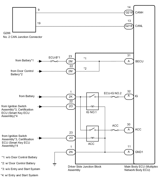
WIRING DIAGRAM
CAUTION / NOTICE / HINT
CAUTION:
When performing the confirmation driving pattern, obey all speed limits and traffic laws.
Note
-
Because the order of diagnosis is important to allow correct diagnosis, make sure to begin troubleshooting using How to Proceed with Troubleshooting when CAN communication system related DTCs are output.
-
Before measuring the resistance of the CAN bus, turn the ignition switch off and leave the vehicle for 1 minute or more without operating the key or any switches, or opening or closing the doors. After that, disconnect the cable from the negative (-) battery terminal and leave the vehicle for 1 minute or more before measuring the resistance.
-
After turning the ignition switch off, waiting time may be required before disconnecting the cable from the negative (-) battery terminal. Therefore, make sure to read the disconnecting the cable from the negative (-) battery terminal notices before proceeding with work.
-
Some parts must be initialized and set when replacing or removing and installing parts.
-
After performing repairs, perform the DTC check procedure and confirm that the DTCs are not output again.
DTC check procedure: Turn the ignition switch to ON and wait for 1 minute or more. Then operate the suspected malfunctioning system and drive the vehicle at 60 km/h (37 mph) or more for 5 minutes or more.
-
After the repair, perform the CAN bus check and check that all the ECUs and sensors connected to the CAN communication system are displayed as normal.
-
Inspect the fuses for circuits related to this system before performing the following procedure.
Tech Tips
-
Before disconnecting related connectors for inspection, push in on each connector body to check that the connector is not loose or disconnected.
-
When a connector is disconnected, check that the terminals and connector body are not cracked, deformed or corroded.
PROCEDURE
-
CHECK FOR OPEN IN CAN BUS WIRE (MAIN BODY ECU [MULTIPLEX NETWORK BODY ECU] BRANCH WIRE)
-
Disconnect the cable from the negative (-) battery terminal.
-
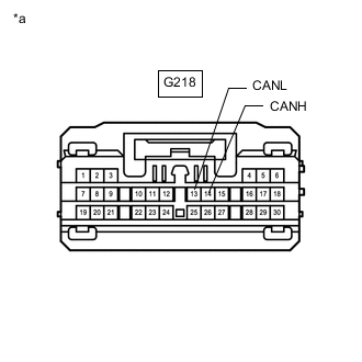
*a Front view of wire harness connector
(to Main Body ECU [Multiplex Network Body ECU])
Disconnect the main body ECU (multiplex network body ECU) connector.
-
Measure the resistance according to the value(s) in the table below.
Standard Resistance Tester Connection Condition Specified Condition G218-14 (CANH) - G218-13 (CANL) Cable disconnected from negative (-) battery terminal 54 to 69 Ω
NG 
REPAIR OR REPLACE CAN BUS BRANCH WIRE OR CONNECTOR
OK 
-
-
CHECK HARNESS AND CONNECTOR (POWER SOURCE CIRCUIT)
-
Remove the main body ECU (multiplex network body ECU).
-
Connect the driver side junction block assembly connectors.
-
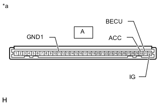
*a Component without harness connected
(Driver Side Junction Block Assembly)
Measure the resistance according to the value(s) in the table below.
Standard Resistance Tester Connection Condition Specified Condition A-11 (GND1) - Body ground Cable disconnected from negative (-) battery terminal Below 1 Ω -
Reconnect the cable to the negative (-) battery terminal.
Note
When disconnecting the cable, some systems need to be initialized after the cable is reconnected.
-
Measure the voltage according to the value(s) in the table below.
Standard Voltage Tester Connection Condition Specified Condition A-31 (BECU) - Body ground Always 11 to 14 V A-30 (ACC) - Body ground Ignition switch ACC 11 to 14 V Ignition switch off Below 1 V A-32 (IG) - Body ground Ignition switch ON 11 to 14 V Ignition switch off Below 1 V
OK
REPLACE MAIN BODY ECU (MULTIPLEX NETWORK BODY ECU) Click here
NG
-
-
CHECK HARNESS AND CONNECTOR (POWER SOURCE CIRCUIT)
-
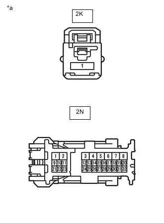
*a Front view of wire harness connector
(to Driver Side Junction Block Assembly)
Disconnect the driver side junction block assembly connectors.
-
Measure the resistance according to the value(s) in the table below.
Standard Resistance Tester Connection Condition Specified Condition 2N-1 (GND1) - Body ground Always Below 1 Ω -
Measure the voltage according to the value(s) in the table below.
Standard Voltage Tester Connection Condition Specified Condition 2K-1 - Body ground Always 11 to 14 V
NG
REPAIR OR REPLACE HARNESS OR CONNECTOR (POWER SOURCE CIRCUIT)
OK
-
-
CHECK HARNESS AND CONNECTOR (POWER SOURCE CIRCUIT)
-
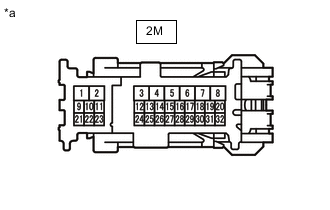
*a Front view of wire harness connector
(to Driver Side Junction Block Assembly)
Disconnect the driver side junction block assembly connector.
-
Measure the voltage according to the value(s) in the table below.
Standard Voltage *1: w/o Door Control BatteryTester Connection Condition Specified Condition 2M-23 - Body ground*1 Always 11 to 14 V 2M-22 - Body ground*2 Always 11 to 14 V
*2: w/ Door Control Battery
Result Result Proceed to OK A NG (w/o Door Control Battery) B NG (w/ Door Control Battery) C
B
REPAIR OR REPLACE HARNESS OR CONNECTOR (POWER SOURCE CIRCUIT)
C
GO TO POWER DOOR LOCK CONTROL SYSTEM Click here
A
-
-
CHECK HARNESS AND CONNECTOR (POWER SOURCE CIRCUIT)
-
Disconnect the driver side junction block assembly connector.

*a Front view of wire harness connector
(to Driver Side Junction Block Assembly)
- - -
Measure the voltage according to the value(s) in the table below.
Standard Voltage Tester Connection Switch Condition Specified Condition 2O-22 - Body ground Ignition switch ON 11 to 14 V Ignition switch off Below 1 V 2O-23 - Body ground Ignition switch ACC 11 to 14 V Ignition switch off Below 1 V Result Result Proceed to OK A NG (w/o Entry and Start System) B NG (w/ Entry and Start System) C
A
REPLACE DRIVER SIDE JUNCTION BLOCK ASSEMBLY Click here
B
REPAIR OR REPLACE HARNESS OR CONNECTOR (POWER SOURCE CIRCUIT)
C
GO TO ENTRY AND START SYSTEM Click here
-