CAN COMMUNICATION SYSTEM(w/ Central Gateway ECU) ECM Communication Stop Mode
DESCRIPTION
| Detection Item | Symptom | Trouble Area |
|---|---|---|
| ECM Communication Stop Mode | Any of the following conditions are met:
|
|
WIRING DIAGRAM
-
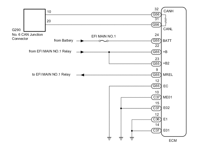
for 1GR-FE with Manual Transmission:
-
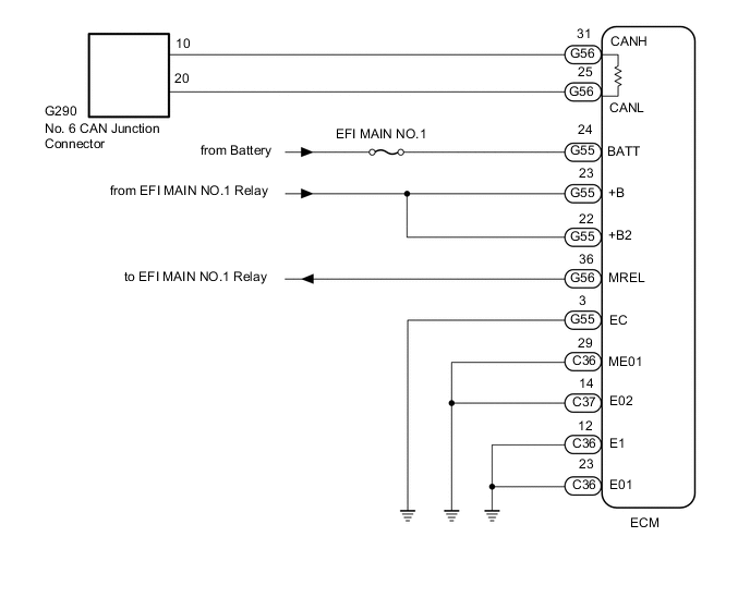
for 1GR-FE with Automatic Transmission:
-
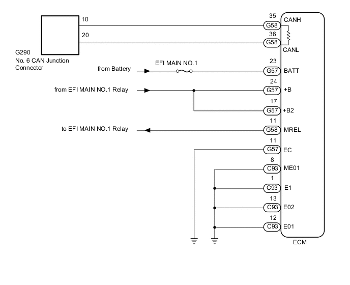
for 1KD-FTV:
-
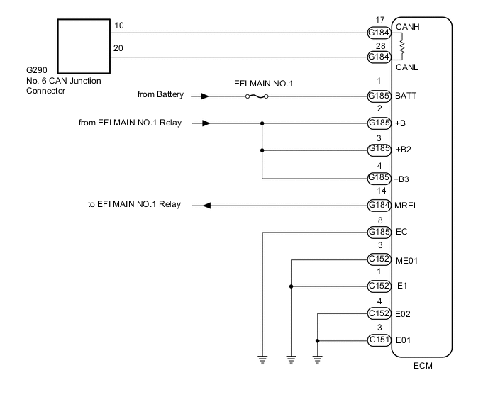
for 1GD-FTV:
-
for 2TR-FE:

CAUTION / NOTICE / HINT
CAUTION:
When performing the confirmation driving pattern, obey all speed limits and traffic laws.
Note
-
Because the order of diagnosis is important to allow correct diagnosis, make sure to begin troubleshooting using How to Proceed with Troubleshooting when CAN communication system related DTCs are output.
-
Before measuring the resistance of the CAN bus, turn the ignition switch off and leave the vehicle for 1 minute or more without operating the key or any switches, or opening or closing the doors. After that, disconnect the cable from the negative (-) battery terminal and leave the vehicle for 1 minute or more before measuring the resistance.
-
After turning the ignition switch off, waiting time may be required before disconnecting the cable from the negative (-) battery terminal. Therefore, make sure to read the disconnecting the cable from the negative (-) battery terminal notices before proceeding with work.
-
Some parts must be initialized and set when replacing or removing and installing parts.
-
After performing repairs, perform the DTC check procedure and confirm that the DTCs are not output again.
DTC check procedure: Turn the ignition switch to ON and wait for 1 minute or more. Then operate the suspected malfunctioning system and drive the vehicle at 60 km/h (37 mph) or more for 5 minutes or more.
-
After the repair, perform the CAN bus check and check that all the ECUs and sensors connected to the CAN communication system are displayed as normal.
-
Inspect the fuses for circuits related to this system before performing the following procedure.
Tech Tips
-
Before disconnecting related connectors for inspection, push in on each connector body to check that the connector is not loose or disconnected.
-
When a connector is disconnected, check that the terminals and connector body are not cracked, deformed or corroded.
PROCEDURE
-
CHECK FOR OPEN IN CAN BUS WIRE (ECM MAIN WIRE)
-
Disconnect the cable from the negative (-) battery terminal.
-
Disconnect the ECM connector.
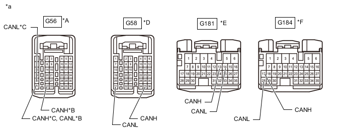
*A for 1GR-FE *B for Manual Transmission *C for Automatic Transmission *D for 1KD-FTV *E for 2TR-FE *F for 1GD-FTV *a Front view of wire harness connector
(to ECM)
- - -
Measure the resistance according to the value(s) in the table below.
Standard Resistance for 1GR-FE with Manual Transmission Tester Connection Condition Specified Condition G56-32 (CANH) - G56-31 (CANL) Cable disconnected from negative (-) battery terminal 108 to 132 Ω for 1GR-FE with Automatic Transmission Tester Connection Condition Specified Condition G56-31 (CANH) - G56-25 (CANL) Cable disconnected from negative (-) battery terminal 108 to 132 Ω for 1KD-FTV Tester Connection Condition Specified Condition G58-35 (CANH) - G58-36 (CANL) Cable disconnected from negative (-) battery terminal 108 to 132 Ω for 1GD-FTV Tester Connection Condition Specified Condition G184-17 (CANH) - G184-28 (CANL) Cable disconnected from negative (-) battery terminal 108 to 132 Ω for 2TR-FE Tester Connection Condition Specified Condition G181-13 (CANH) - G181-14 (CANL) Cable disconnected from negative (-) battery terminal 108 to 132 Ω
NG 
REPAIR OR REPLACE CAN BUS MAIN WIRE OR CONNECTOR
OK 
-
-
CHECK HARNESS AND CONNECTOR (POWER SOURCE CIRCUIT)
-
for 1GR-FE with Manual Transmission:
-
Disconnect the ECM connectors.
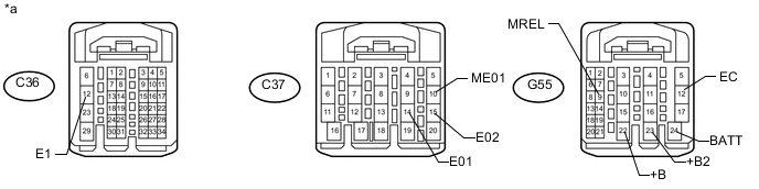
*a Front view of wire harness connector
(to ECM)
- - -
Measure the resistance according to the value(s) in the table below.
Standard Resistance Tester Connection Condition Specified Condition C36-12 (E1) - Body ground Cable disconnected from negative (-) battery terminal Below 1 Ω C37-14 (E01) - Body ground Cable disconnected from negative (-) battery terminal Below 1 Ω C37-15 (E02) - Body ground Cable disconnected from negative (-) battery terminal Below 1 Ω C37-10 (ME01) - Body ground Cable disconnected from negative (-) battery terminal Below 1 Ω G55-12 (EC) - Body ground Cable disconnected from negative (-) battery terminal Below 1 Ω -
Reconnect the cable to the negative (-) battery terminal.
Note
When disconnecting the cable, some systems need to be initialized after the cable is reconnected.
-
Measure the voltage according to the value(s) in the table below.
Standard Voltage Tester Connection Condition Specified Condition G55-24 (BATT) - Body ground Always 11 to 14 V G55-23 (+B2) - Body ground Battery positive (+) voltage applied to terminal G55-9 (MREL) 11 to 14 V G55-22 (+B) - Body ground Battery positive (+) voltage applied to terminal G55-9 (MREL) 11 to 14 V
-
-
for 1GR-FE and Automatic Transmission:
-
Disconnect the ECM connectors.
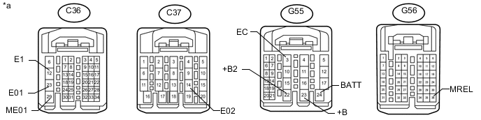
*a Front view of wire harness connector
(to ECM)
- - -
Measure the resistance according to the value(s) in the table below.
Standard Resistance Tester Connection Condition Specified Condition C36-12 (E1) - Body ground Cable disconnected from negative (-) battery terminal Below 1 Ω C36-23 (E01) - Body ground Cable disconnected from negative (-) battery terminal Below 1 Ω C37-14 (E02) - Body ground Cable disconnected from negative (-) battery terminal Below 1 Ω C36-29 (ME01) - Body ground Cable disconnected from negative (-) battery terminal Below 1 Ω G55-3 (EC) - Body ground Cable disconnected from negative (-) battery terminal Below 1 Ω -
Reconnect the cable to the negative (-) battery terminal.
Note
When disconnecting the cable, some systems need to be initialized after the cable is reconnected.
-
Measure the voltage according to the value(s) in the table below.
Standard Voltage Tester Connection Condition Specified Condition G55-24 (BATT) - Body ground Always 11 to 14 V G55-22 (+B2) - Body ground Battery positive (+) voltage applied to terminal G56-36 (MREL) 11 to 14 V G55-23 (+B) - Body ground Battery positive (+) voltage applied to terminal G56-36 (MREL) 11 to 14 V
-
-
for 1KD-FTV:
-
Disconnect the ECM connectors.
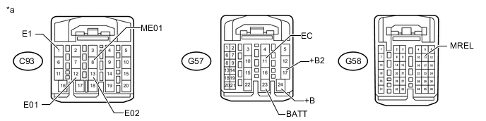
*a Front view of wire harness connector
(to ECM)
- - -
Measure the resistance according to the value(s) in the table below.
Standard Resistance Tester Connection Condition Specified Condition C93-1 (E1) - Body ground Cable disconnected from negative (-) battery terminal Below 1 Ω C93-12 (E01) - Body ground Cable disconnected from negative (-) battery terminal Below 1 Ω C93-13 (E02) - Body ground Cable disconnected from negative (-) battery terminal Below 1 Ω C93-8 (ME01) - Body ground Cable disconnected from negative (-) battery terminal Below 1 Ω G57-11 (EC) - Body ground Cable disconnected from negative (-) battery terminal Below 1 Ω -
Reconnect the cable to the negative (-) battery terminal.
Note
When disconnecting the cable, some systems need to be initialized after the cable is reconnected.
-
Measure the voltage according to the value(s) in the table below.
Standard Voltage Tester Connection Condition Specified Condition G57-23 (BATT) - Body ground Always 11 to 14 V G57-17 (+B2) - Body ground Battery positive (+) voltage applied to terminal G58-11 (MREL) 11 to 14 V G57-24 (+B) - Body ground Battery positive (+) voltage applied to terminal G58-11 (MREL) 11 to 14 V
-
-
for 1GD-FTV:
-
Disconnect the ECM connectors.
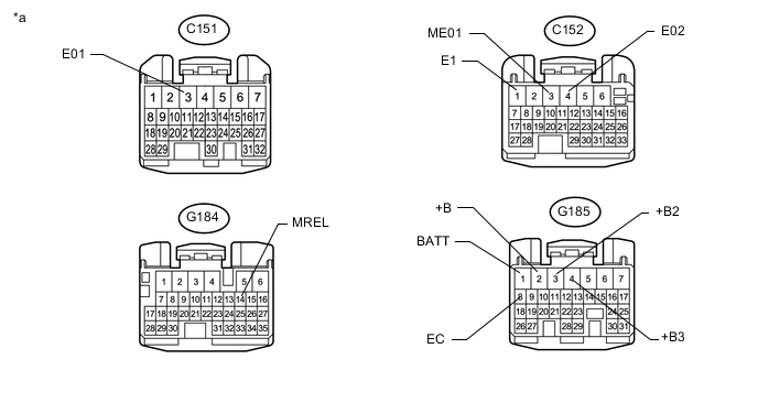
*a Front view of wire harness connector
(to ECM)
- - -
Measure the resistance according to the value(s) in the table below.
Standard Resistance Tester Connection Condition Specified Condition C152-1 (E1) - Body ground Cable disconnected from negative (-) battery terminal Below 1 Ω C151-3 (E01) - Body ground Cable disconnected from negative (-) battery terminal Below 1 Ω C152-4 (E02) - Body ground Cable disconnected from negative (-) battery terminal Below 1 Ω C152-3 (ME01) - Body ground Cable disconnected from negative (-) battery terminal Below 1 Ω G185-8 (EC) - Body ground Cable disconnected from negative (-) battery terminal Below 1 Ω -
Reconnect the cable to the negative (-) battery terminal.
Note
When disconnecting the cable, some systems need to be initialized after the cable is reconnected.
-
Measure the voltage according to the value(s) in the table below.
Standard Voltage Tester Connection Condition Specified Condition G185-1 (BATT) - Body ground Always 11 to 14 V G185-2 (+B) - Body ground Battery positive (+) voltage applied to terminal G184-14 (MREL) 11 to 14 V G185-3 (+B2) - Body ground Battery positive (+) voltage applied to terminal G184-14 (MREL) 11 to 14 V G185-4 (+B3) - Body ground Battery positive (+) voltage applied to terminal G184-14 (MREL) 11 to 14 V
-
-
for 2TR-FE:
-
Disconnect the ECM connectors.
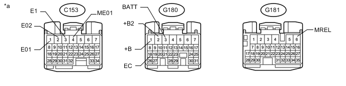
*a Front view of wire harness connector
(to ECM)
- - -
Measure the resistance according to the value(s) in the table below.
Standard Resistance Tester Connection Condition Specified Condition C153-3 (E1) - Body ground Cable disconnected from negative (-) battery terminal Below 1 Ω C153-1 (E01) - Body ground Cable disconnected from negative (-) battery terminal Below 1 Ω C153-2 (E02) - Body ground Cable disconnected from negative (-) battery terminal Below 1 Ω C153-4 (ME01) - Body ground Cable disconnected from negative (-) battery terminal Below 1 Ω G180-18 (EC) - Body ground Cable disconnected from negative (-) battery terminal Below 1 Ω -
Reconnect the cable to the negative (-) battery terminal.
Note
When disconnecting the cable, some systems need to be initialized after the cable is reconnected.
-
Measure the voltage according to the value(s) in the table below.
Standard Voltage Tester Connection Condition Specified Condition G180-3 (BATT) - Body ground Always 11 to 14 V G180-1 (+B) - Body ground Battery positive (+) voltage applied to terminal G181-6 (MREL) 11 to 14 V G180-2 (+B2) - Body ground Battery positive (+) voltage applied to terminal G181-6 (MREL) 11 to 14 V
-
OK
REPLACE ECM for 1GR-FE: Click here
REPLACE ECM for 1KD-FTV: Click here
REPLACE ECM for 1GD-FTV: Click here
REPLACE ECM for 2TR-FE: Click hereNG
REPAIR OR REPLACE HARNESS OR CONNECTOR (POWER SOURCE CIRCUIT)
-