CAN COMMUNICATION SYSTEM(w/ Central Gateway ECU) TERMINALS OF ECU
Note
-
After turning the ignition switch off, waiting time may be required before disconnecting the cable from the negative (-) battery terminal. Therefore, make sure to read the disconnecting the cable from the negative (-) battery terminal notices before proceeding with work.
-
Before measuring the resistance of the CAN bus, turn the ignition switch off and leave the vehicle for 1 minute or more without operating the key or any switches, or opening or closing the doors. After that, disconnect the cable from the negative (-) battery terminal and leave the vehicle for 1 minute or more before measuring the resistance.
-
This section describes the standard values for all CAN related components.
Tech Tips
-
The systems (ECUs and sensors) that use CAN communication vary depending on the vehicle and optional equipment. Check which systems (ECUs and sensors) are installed to the vehicle.
-
Operating the ignition switch, any other switches or a door triggers related ECU and sensor communication on the CAN. This communication will cause the resistance value to change.
-
Even after DTCs are cleared, if a DTC is stored again after driving the vehicle for a while, the malfunction may be occurring due to vibration of the vehicle. In such a case, wiggling the ECUs or wire harness while performing the inspection below may help determine the cause of the malfunction.
-
NO. 1 CAN JUNCTION CONNECTOR
-
Check the No. 1 CAN junction connector (for LHD).
-

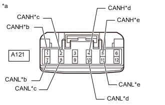
*a Front view of wire harness connector
(to No. 1 CAN Junction Connector)
*b for Suspension Control ECU (w/ Air Suspension System) *c for Millimeter Wave Radar Sensor Assembly (w/ Pre-crash Safety System) *d for No. 1 CAN Junction Terminal *e for No. 3 CAN Junction Connector Connection diagram
-
Check the connection diagram of the components which are connected to the No. 1 CAN junction connector.
Terminal No. (Symbol) Wiring Color Connected to A121-1 (CANH) GR Suspension control ECU*1 A121-7 (CANL) W A121-2 (CANH) V Millimeter wave radar sensor assembly*2 A121-8 (CANL) W A121-4 (CANH) LG No. 1 CAN junction terminal A121-10 (CANL) W A121-5 (CANH) B No. 3 CAN junction connector A121-11 (CANL) W *1: w/ Air Suspension System
*2: w/ Pre-crash Safety System
-
-
Check the No. 1 CAN junction connector (for RHD).
-
*a Front view of wire harness connector
(to No. 1 CAN Junction Connector)
*b for Suspension Control ECU (w/ Air Suspension System) *c for Millimeter Wave Radar Sensor Assembly (w/ Pre-crash Safety System) *d for No. 7 CAN Junction Connector *e for Central Gateway ECU (Network Gateway ECU) Connection diagram
-
Check the connection diagram of the components which are connected to the No. 1 CAN junction connector.
Terminal No. (Symbol) Wiring Color Connected to A121-1 (CANH) GR Suspension control ECU*1 A121-7 (CANL) W A121-2 (CANH) V Millimeter wave radar sensor assembly*2 A121-8 (CANL) W A121-4 (CANH) LG No. 7 CAN junction connector A121-10 (CANL) W A121-5 (CANH) B Central gateway ECU (network gateway ECU) A121-11 (CANL) W *1: w/ Air Suspension System
*2: w/ Pre-crash Safety System
-
-
-
NO. 2 CAN JUNCTION CONNECTOR
-
Check the No. 2 CAN junction connector.
-
Connection diagram
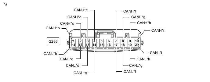
*a Front view of wire harness connector
(to No. 2 CAN Junction Connector)
*b for No. 6 CAN Junction Connector *c for Spiral Cable with Steering Angle Sensor *d for Airbag Sensor Assembly *e for No. 1 Headlight ECU Sub-assembly LH (for LHD with LED Headlight) *f for Tire Pressure Warning ECU and Receiver (for LHD with Tire Pressure Warning System) *g for Combination Meter Assembly *h for Main Body ECU (Multiplex Network Body ECU) *i for Master Cylinder Solenoid (Skid Control ECU) (except 2TR-FE) - - -
Check the connection diagram of the components which are connected to the No. 2 CAN junction connector.
Terminal No. (Symbol) Wiring Color Connected to G286-1 (CANH) GR No. 6 CAN junction connector G286-11 (CANL) W G286-2 (CANH) G Spiral cable with steering angle sensor G286-12 (CANL) W G286-3 (CANH) Y Airbag sensor assembly G286-13 (CANL) W G286-4 (CANH) B No. 1 headlight ECU sub-assembly LH*1 G286-14 (CANL) W G286-7 (CANH) LG Tire pressure warning ECU and receiver*2 G286-17 (CANL) W G286-8 (CANH) V Combination meter assembly G286-18 (CANL) W G286-9 (CANH) L Main body ECU (multiplex network body ECU) G286-19 (CANL) W G286-10 (CANH) B Master cylinder solenoid (skid control ECU)*3 G286-20 (CANL) W *1: for LHD with LED Headlight
*2: for LHD with Tire Pressure Warning System
*3: except 2TR-FE
-
-
-
NO. 3 CAN JUNCTION CONNECTOR
-
Check the No. 3 CAN junction connector (for LHD).
-
Connection diagram
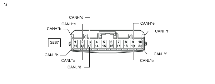
*a Front view of wire harness connector
(to No. 3 CAN Junction Connector)
*b for No. 7 CAN Junction Connector *c for Stabilizer Control ECU (w/ Kinetic Dynamic Suspension System) *d for Forward Recognition Camera (w/ Pre-crash Safety System) *e for Blind Spot Monitor Sensor LH (w/ Blind Spot Monitor System) *f for No. 1 CAN Junction Connector -
Check the connection diagram of the components which are connected to the No. 3 CAN junction connector.
Terminal No. Wiring Color Connected to G287-1 (CANH) P No. 7 CAN junction connector G287-11 (CANL) W G287-2 (CANH) V Stabilizer control ECU*1 G287-12 (CANL) W G287-3 (CANH) GR Forward recognition camera*2 G287-13 (CANL) W G287-9 (CANH) LG Blind spot monitor sensor LH*3 G287-19 (CANL) W G287-10 (CANH) B No. 1 CAN junction connector G287-20 (CANL) W *1: w/ Kinetic Dynamic Suspension System
*2: w/ Pre-crash Safety System
*3: w/ Blind Spot Monitor System
-
-
Check the No. 3 CAN junction connector (for RHD).
-
Connection diagram
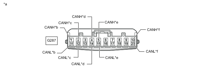
*a Front view of wire harness connector
(to No. 3 CAN Junction Connector)
*b for No. 7 CAN Junction Connector *c for Stabilizer Control ECU (w/ Kinetic Dynamic Suspension System) *d for Parking Assist ECU (w/ Parking Assist Monitor System) *e for Clearance Warning ECU Assembly (w/ TOYOTA Parking Assist-sensor System [for 4 Sensor Type with Multi-display]) *f for No. 1 CAN Junction Terminal -
Check the connection diagram of the components which are connected to the No. 3 CAN junction connector.
Terminal No. Wiring Color Connected to G287-1 (CANH) P No. 7 CAN junction connector G287-11 (CANL) W G287-2 (CANH) V Stabilizer control ECU*1 G287-12 (CANL) W G287-4 (CANH) B Parking assist ECU*2 G287-14 (CANL) W G287-5 (CANH) R Clearance warning ECU assembly*3 G287-15 (CANL) W G287-10 (CANH) LG No. 1 CAN junction connector G287-20 (CANL) W *1: w/ Kinetic Dynamic Suspension System
*2: w/ Parking Assist Monitor System
*3: w/ TOYOTA Parking Assist-sensor System (for 4 Sensor Type with Multi-display)
-
-
-
NO. 4 CAN JUNCTION CONNECTOR
-
Check the No. 4 CAN junction connector.
-
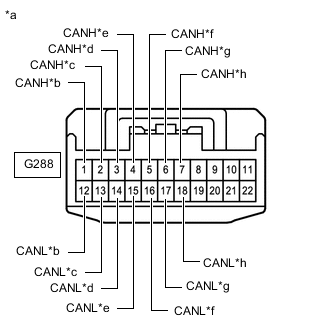
*a Front view of wire harness connector
(to No. 4 CAN Junction Connector)
*b for Outer Mirror Control ECU Assembly RH (w/ Reverse Shift-linked Mirror) *c for Front Power Seat Switch (Power Seat Control ECU) (w/ Seat Memory) *d for Multiplex Tilt and Telescopic ECU (for Power Tilt and Power Telescopic Steering Column) *e for Main Body ECU (Multiplex Network Body ECU) *f for Rear Television Camera Assembly (w/ Multi-terrain Monitor System) *g for Outer Mirror Control ECU Assembly LH (w/ Reverse Shift-linked Mirror) *h for No. 2 CAN Junction Terminal Connection diagram
-
Check the connection diagram of the components which are connected to the No. 4 CAN junction connector.
Terminal No. (Symbol) Wiring Color Connected to G288-1 (CANH) G Outer mirror control ECU assembly RH*1 G288-12 (CANL) W G288-2 (CANH) L Front power seat switch (power seat control ECU)*4 G288-13 (CANL) W G288-3 (CANH) GR Multiplex tilt and telescopic ECU*2 G288-14 (CANL) W G288-4 (CANH) P Main body ECU (multiplex network body ECU) G288-15 (CANL) W G288-5 (CANH) B Rear television camera assembly*3 G288-16 (CANL) W G288-6 (CANH) R Outer mirror control ECU assembly LH*1 G288-17 (CANL) W G288-7 (CANH) LG No. 2 CAN junction terminal G288-18 (CANL) W *1: w/ Reverse Shift-linked Mirror
*2: for Power Tilt and Power Telescopic Steering Column
*3: w/ Multi-terrain Monitor System
*4: w/ Seat Memory
-
-
-
NO. 5 CAN JUNCTION CONNECTOR
-
Check the No. 5 CAN junction connector.
-
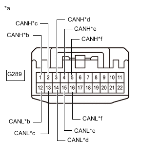
*a Front view of wire harness connector
(to No. 5 CAN Junction Connector)
*b for Central Gateway ECU (Network Gateway ECU) *c for Central Gateway ECU (Network Gateway ECU) *d
-
for Navigation Receiver Assembly (EMVN ECU) (w/ Navigation System)
-
for Radio and Display Receiver Assembly (EMVN ECU) (w/ Audio and Visual System)
*e for Telematics Transceiver (w/ Telematics Transceiver) *f for Bus Buffer ECU (w/ Bus Buffer ECU) Connection diagram
-
-
Check the connection diagram of the components which are connected to the No. 5 CAN junction connector.
Terminal No. (Symbol) Wiring Color Connected to G289-1 (CANH) G Central gateway ECU (network gateway ECU) G289-12 (CANL) W G289-2 (CANH) L Central gateway ECU (network gateway ECU) G289-13 (CANL) W G289-3 (CANH) R
-
Navigation receiver assembly (EMVN ECU)*1
-
Radio and display receiver assembly (EMVN ECU)*2
G289-14 (CANL) W G289-4 (CANH) P Telematics transceiver*3 G289-15 (CANL) W G289-5 (CANH) B Bus buffer ECU*4 G289-16 (CANL) W *1: w/ Navigation System
*2: w/ Audio and Visual System
*3: w/ Telematics Transceiver
*4: w/ Bus Buffer ECU
-
-
-
-
NO. 6 CAN JUNCTION CONNECTOR
-
Check the No. 6 CAN junction connector.
-
Connection diagram
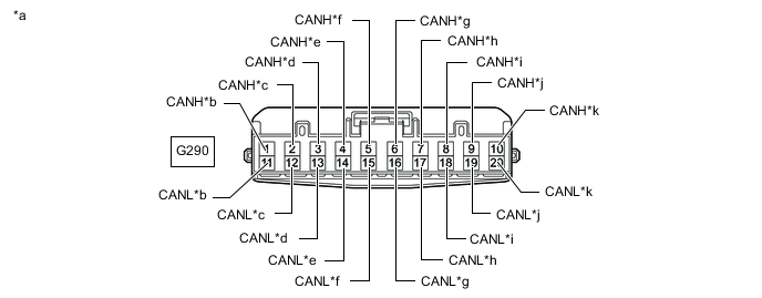
*a Front view of wire harness connector
(to No. 6 CAN Junction Connector)
*b for No. 2 CAN Junction Connector *c for 4 Wheel Drive Control ECU (4WD Control ECU) *d for Certification ECU (Smart Key ECU Assembly) (w/ Entry and Start System) *e for No. 1 Headlight ECU Sub-assembly LH (for RHD with LED Headlight) *f for Tire Pressure Warning ECU and Receiver (for RHD with Tire Pressure Warning System) *g for Central Gateway ECU (Network Gateway ECU) *h for Air Conditioning Amplifier Assembly *i for Power Steering ECU Assembly *j for Brake Actuator Assembly (Skid Control ECU) (for 2TR-FE) *k for ECM - - -
Check the connection diagram of the components which are connected to the No. 6 CAN junction connector.
Terminal No. (Symbol) Wiring Color Connected to G290-1 (CANH) GR No. 2 CAN junction connector G290-11 (CANL) W G290-2 (CANH) G 4 Wheel drive control ECU (4WD control ECU) G290-12 (CANL) W G290-3 (CANH) P Certification ECU (smart key ECU assembly)*1 G290-13 (CANL) W G290-4 (CANH) V No. 1 headlight ECU sub-assembly LH*2 G290-14 (CANL) W G290-5 (CANH) LG Tire pressure warning ECU and receiver*3 G290-15 (CANL) W G290-6 (CANH) BR Central gateway ECU (network gateway ECU) G290-16 (CANL) W G290-7 (CANH) V Air conditioning amplifier assembly G290-17 (CANL) W G290-8 (CANH) L Power steering ECU assembly G290-18 (CANL) W G290-9 (CANH) R Brake actuator assembly (skid control ECU)*4 G290-19 (CANL) W G290-10 (CANH) LG ECM G290-20 (CANL) W *1: w/ Entry and Start System
*2: for RHD with LED Headlight
*3: for RHD with Tire Pressure Warning System
*4: for 2TR-FE
-
-
-
NO. 7 CAN JUNCTION CONNECTOR
-
Check the No. 7 CAN junction connector (for LHD).
-
Connection diagram
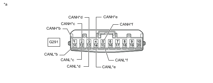
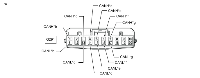
*a Front view of wire harness connector
(to No. 7 CAN Junction Connector)
*b for No. 3 CAN Junction Connector *c for Central Gateway ECU (Network Gateway ECU) *d for Parking Assist ECU (w/ Parking Assist Monitor System) *e for Driving Support ECU Assembly (w/ Pre-crash Safety System) *f for Clearance Warning ECU Assembly (w/ TOYOTA Parking Assist-sensor System [w/ Multi-display]) -
Check the connection diagram of the components which are connected to the No. 7 CAN junction connector.
Terminal No. (Symbol) Wiring Color Connected to G291-1 (CANH) P No. 3 CAN junction connector G291-11 (CANL) W G291-2 (CANH) V Central gateway ECU (network gateway ECU) G291-12 (CANL) W G291-3 (CANH) B Parking assist ECU*1 G291-13 (CANL) W G291-4 (CANH) G Driving support ECU assembly*2 G291-14 (CANL) W G291-5 (CANH) R Clearance warning ECU assembly*3 G291-15 (CANL) W *1: w/ Parking Assist Monitor System
*2: w/ Pre-crash Safety System
*3: w/ TOYOTA Parking Assist-sensor System (w/ Multi-display)
-
-
Check the No. 7 CAN junction connector (for RHD).
-
Connection diagram
*a Front view of wire harness connector
(to No. 7 CAN Junction Connector)
*b for No. 3 CAN Junction Connector *c for No. 1 CAN Junction Connector *d for Driving Support ECU Assembly (w/ Pre-crash Safety System) *e for Forward Recognition Camera (w/ Pre-crash Safety System) *f for Blind Spot Monitor Sensor LH (w/ Blind Spot Monitor System) *g for Clearance Warning ECU Assembly (w/ TOYOTA Parking Assist-sensor System [for 8 Sensor Type with Multi-display]) - - -
Check the connection diagram of the components which are connected to the No. 7 CAN junction connector.
Terminal No. (Symbol) Wiring Color Connected to G291-1 (CANH) P No. 3 CAN junction connector G291-11 (CANL) W G291-3 (CANH) LG No. 1 CAN junction connector G291-13 (CANL) W G291-4 (CANH) G Driving support ECU assembly*1 G291-14 (CANL) W G291-5 (CANH) GR Forward recognition camera*1 G291-15 (CANL) W G291-6 (CANH) LG Blind spot monitor sensor LH*2 G291-16 (CANL) W G291-7 (CANH) R Clearance warning ECU assembly*3 G291-17 (CANL) W *1: w/ Pre-crash Safety System
*2: w/ Blind Spot Monitor System
*3: w/ TOYOTA Parking Assist-sensor System (for 8 Sensor Type with Multi-display)
-
-
-
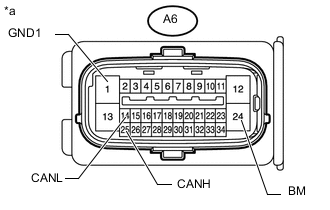
NO. 1 CAN JUNCTION TERMINAL
-
Check the No. 1 CAN junction terminal.
-
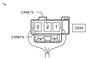
*a Rear view of wire harness connector
(to No. 1 CAN Junction Terminal)
*b
-
for No. 1 CAN Junction Connector (for LHD)
-
for No. 3 CAN Junction Connector (for RHD)
Connection diagram
-
-
Check the connection diagram of the components which are connected to the No. 1 CAN junction terminal.
Terminal No. (Symbol) Wiring Color Connected to G298-3 (CANH) LG
-
No. 1 CAN junction connector*1
-
No. 3 CAN junction connector*2
G298-2 (CANL) W *1: for LHD
*2: for RHD
-
-
-
-
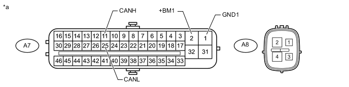
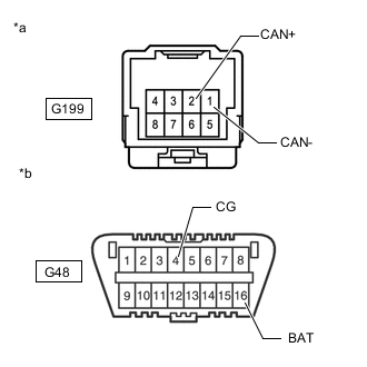
NO. 2 CAN JUNCTION TERMINAL
-
Check the No. 2 CAN junction terminal.
-
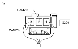
*a Rear view of wire harness connector
(to No. 2 CAN Junction Terminal)
*b for No. 4 CAN Junction Connector Connection diagram
-
Check the connection diagram of the components which are connected to the No. 2 CAN junction terminal.
Terminal No. (Symbol) Wiring Color Connected to G299-3 (CANP) LG No. 4 CAN junction connector G299-2 (CANN) W
-
-
-
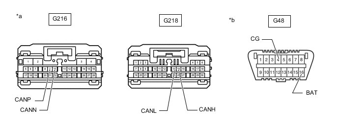
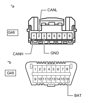
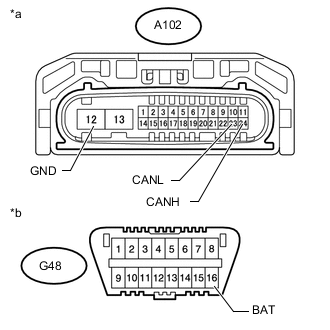
DLC3
-
Disconnect the cable from the negative (-) battery terminal.
-
Measure the resistance according to the value(s) in the table below.
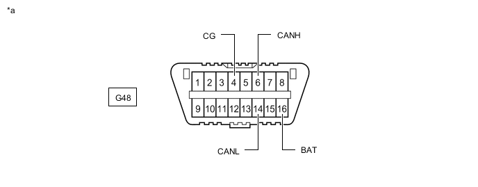
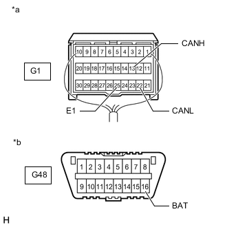
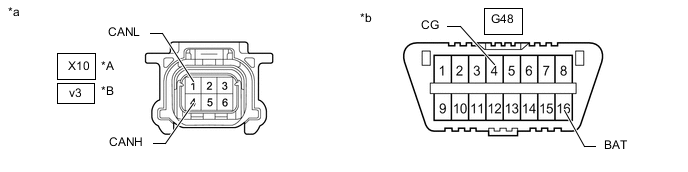
*a Front view of DLC3 - -
-
-
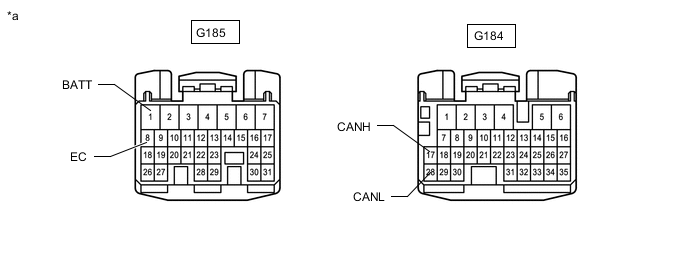
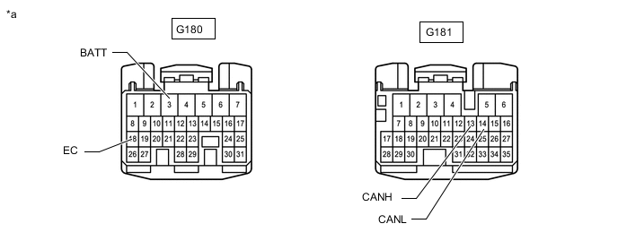
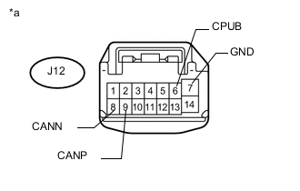
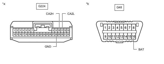
CENTRAL GATEWAY ECU (NETWORK GATEWAY ECU)
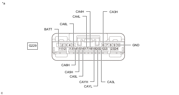
*a Component without harness connected
(Central Gateway ECU [Network Gateway ECU])
- -
-
Disconnect the cable from the negative (-) battery terminal.
-
Disconnect the central gateway ECU (network gateway ECU) connector.
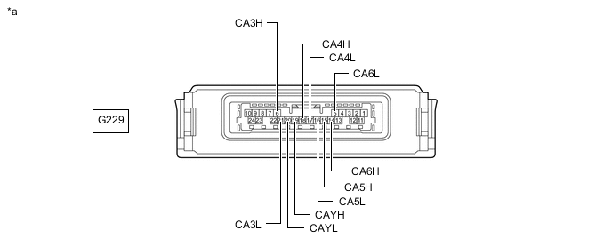
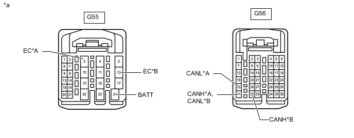
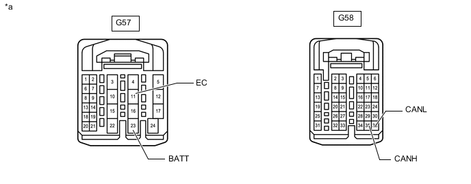
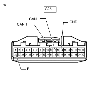
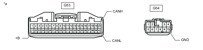
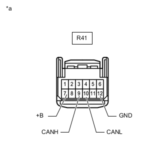
*a Front view of wire harness connector
(to Central Gateway ECU [Network Gateway ECU])
- - -
Measure the resistance according to the value(s) in the table below.
-
-
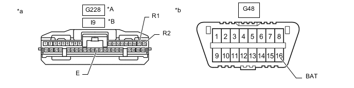
ECM (for 1GR-FE)
Refer to Terminals of ECU.
-
Disconnect the cable from the negative (-) battery terminal.
-
Disconnect the ECM connectors.
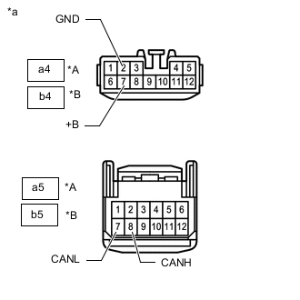
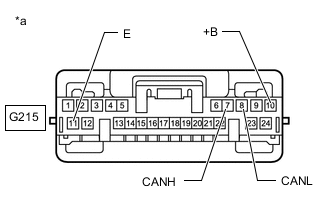
*A for Automatic Transmission *B for Manual Transmission *a Front view of wire harness connector
(to ECM)
- - -
Measure the resistance according to the value(s) in the table below.
-
-
ECM (for 1KD-FTV)
Refer to Terminals of ECU.
-
Disconnect the cable from the negative (-) battery terminal.
-
Disconnect the ECM connectors.
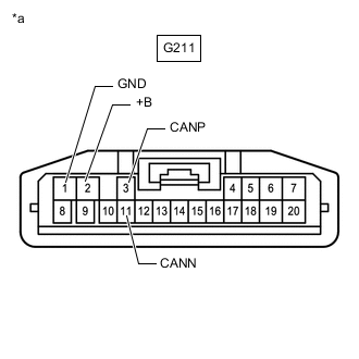
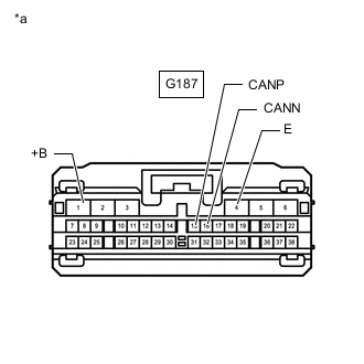
*a Front view of wire harness connector
(to ECM)
- - -
Measure the resistance according to the value(s) in the table below.
-
-
ECM (for 1GD-FTV)
Refer to Terminals of ECU.
-
Disconnect the cable from the negative (-) battery terminal.
-
Disconnect the ECM connectors.
*a Front view of wire harness connector
(to ECM)
- - -
Measure the resistance according to the value(s) in the table below.
-
-
ECM (for 2TR-FE)
Refer to Terminals of ECU.
-
Disconnect the cable from the negative (-) battery terminal.
-
Disconnect the ECM connectors.
*a Front view of wire harness connector
(to ECM)
- - -
Measure the resistance according to the value(s) in the table below.
-
-
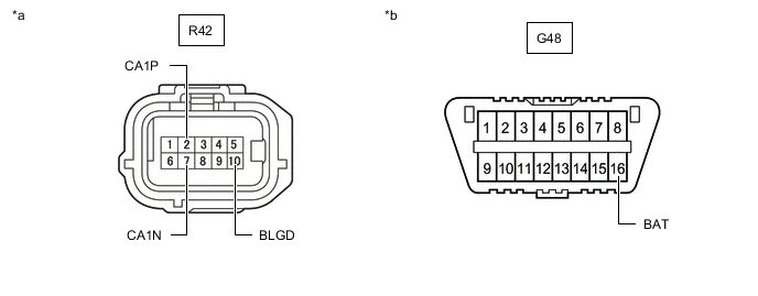
BRAKE ACTUATOR ASSEMBLY (SKID CONTROL ECU) (for 2TR-FE)
Refer to Terminals of ECU.
-
*a Front view of wire harness connector
(to Brake Actuator Assembly [Skid Control ECU])
Disconnect the brake actuator assembly (skid control ECU) connector.
-
Measure the resistance according to the value(s) in the table below.
-
-
MASTER CYLINDER SOLENOID (SKID CONTROL ECU) (except 2TR-FE)
Refer to Terminals of ECU.
-
Disconnect the master cylinder solenoid (skid control ECU) connector.
*a Front view of wire harness connector
(to Master Cylinder Solenoid [Skid Control ECU])
- - -
Measure the resistance according to the value(s) in the table below.
-
-
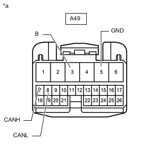
AIR CONDITIONING AMPLIFIER ASSEMBLY
Refer to Terminals of ECU.
for Automatic Air Conditioning System: Click here
for Manual Air Conditioning System: Click here
-
Disconnect the cable from the negative (-) battery terminal.
-
*a Front view of wire harness connector
(to Air Conditioning Amplifier Assembly)
Disconnect the air conditioning amplifier assembly connector.
-
Measure the resistance according to the value(s) in the table below.
-
-
AIRBAG SENSOR ASSEMBLY
Refer to Terminals of ECU.
-
Disconnect the cable from the negative (-) battery terminal, and wait for at least 90 seconds.
-
*a Rear view of wire harness connector
(to Airbag Sensor Assembly)
*b Front view of DLC3 Disconnect the airbag sensor assembly connector.
-
Measure the resistance according to the value(s) in the table below.
-
-
COMBINATION METER ASSEMBLY
Refer to Terminals of ECU.
-
Disconnect the cable from the negative (-) battery terminal.
-
*a Front view of wire harness connector
(to Combination Meter Assembly)
Disconnect the combination meter assembly connector.
-
Measure the resistance according to the value(s) in the table below.
-
-
SPIRAL CABLE WITH STEERING ANGLE SENSOR
-
Disconnect the cable from the negative (-) battery terminal.
-
*a Front view of wire harness connector
(to Spiral Cable with Steering Angle Sensor)
Disconnect the spiral cable with steering angle sensor connector.
-
Measure the resistance according to the value(s) in the table below.
-
-
4 WHEEL DRIVE CONTROL ECU (4WD CONTROL ECU)
Refer to Terminals of ECU.
-
Disconnect the cable from the negative (-) battery terminal.
-
Disconnect the 4 wheel drive control ECU (4WD control ECU) connectors.
*a Front view of wire harness connector
(to 4 Wheel Drive Control ECU [4WD Control ECU])
- - -
Measure the resistance according to the value(s) in the table below.
-
-
FRONT POWER SEAT SWITCH (POWER SEAT CONTROL ECU) (w/ Seat Memory)
Refer to Terminals of ECU.
-
Disconnect the cable from the negative (-) battery terminal.
-
*A for RHD *B for LHD *a Front view of wire harness connector
(to Front Power Seat Switch [Power Seat Control ECU])
Disconnect the front power seat switch (power seat control ECU) connectors.
-
Measure the resistance according to the value(s) in the table below.
-
-
MULTIPLEX TILT AND TELESCOPIC ECU (w/ Seat Memory)
Refer to Terminals of ECU.
-
Disconnect the cable from the negative (-) battery terminal.
-
*a Front view of wire harness connector
(to Multiplex Tilt and Telescopic ECU)
Disconnect the multiplex tilt and telescopic ECU connector.
-
Measure the resistance according to the value(s) in the table below.
-
-
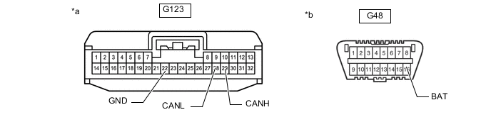
MAIN BODY ECU (MULTIPLEX NETWORK BODY ECU)
Refer to Terminals of ECU.
for Halogen Headlight: Click here
for LED Headlight: Click here
-
Disconnect the cable from the negative (-) battery terminal.
-
Disconnect the main body ECU (multiplex network body ECU) connectors.
*a Front view of wire harness connector
(to Main Body ECU [Multiplex Network Body ECU])
*b Front view of DLC3 -
Measure the resistance according to the value(s) in the table below.
-
-
OUTER MIRROR CONTROL ECU ASSEMBLY LH (w/ Reverse Shift-linked Mirror)
Refer to Terminals of ECU.
-
Disconnect the cable from the negative (-) battery terminal.
-

*a Front view of wire harness connector
(to Outer Mirror Control ECU Assembly LH)
Disconnect the outer mirror control ECU assembly LH connector.
-
Measure the resistance according to the value(s) in the table below.
-
-
OUTER MIRROR CONTROL ECU ASSEMBLY RH (w/ Reverse Shift-linked Mirror)
Refer to Terminals of ECU.
-
Disconnect the cable from the negative (-) battery terminal.
-
*a Front view of wire harness connector
(to Outer Mirror Control ECU Assembly RH)
Disconnect the outer mirror control ECU assembly RH connector.
-
Measure the resistance according to the value(s) in the table below.
-
-
POWER STEERING ECU ASSEMBLY
Refer to Terminals of ECU.
-
Disconnect the cable from the negative (-) battery terminal.
-
*a Front view of wire harness connector
(to Power Steering ECU Assembly)
*b Front view of DLC3 Disconnect the power steering ECU assembly connector.
-
Measure the resistance according to the value(s) in the table below.
-
-
SUSPENSION CONTROL ECU (w/ Air Suspension System)
Refer to Terminals of ECU.
-
Disconnect the cable from the negative (-) battery terminal.
-
*a Front view of wire harness connector
(to Suspension Control ECU)
Disconnect the suspension control ECU connector.
-
Measure the resistance according to the value(s) in the table below.
-
-
BLIND SPOT MONITOR SENSOR LH (w/ Blind Spot Monitor Sensor)
Refer to Terminals of ECU.
-
Disconnect the cable from the negative (-) battery terminal.
-
Disconnect the blind spot monitor sensor LH connector.
*a Front view of wire harness connector
(to Blind Spot Monitor Sensor LH)
*b Front view of DLC3 -
Measure the resistance according to the value(s) in the table below.
-
-
FORWARD RECOGNITION CAMERA (w/ Pre-crash Safety System)
Refer to Terminals of ECU.
-
Disconnect the cable from the negative (-) battery terminal.
-
Disconnect the forward recognition camera connector.
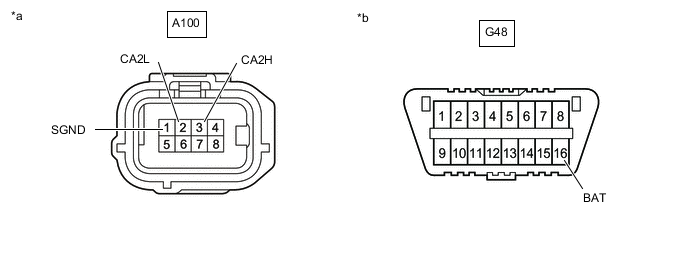
*a Front view of wire harness connector
(to Forward Recognition Camera)
*b Front view of DLC3 -
Measure the resistance according to the value(s) in the table below.
-
-
MILLIMETER WAVE RADAR SENSOR ASSEMBLY (w/ Pre-crash Safety System)
Refer to Terminals of ECU.
-
Disconnect the cable from the negative (-) battery terminal.
-
Disconnect the millimeter wave radar sensor assembly connector.
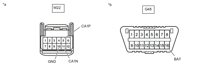
*a Front view of wire harness connector
(to Millimeter Wave Radar Sensor Assembly)
*b Front view of DLC3 -
Measure the resistance according to the value(s) in the table below.
-
-
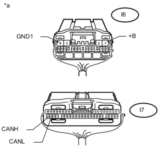
RADIO AND DISPLAY RECEIVER ASSEMBLY (w/ Audio and Visual System)
Refer to Terminals of ECU.
-
*a Front view of wire harness connector
(to Radio and Display Receiver Assembly)
Disconnect the radio and display receiver assembly connectors.
-
Measure the resistance according to the value(s) in the table below.
-
-
NAVIGATION RECEIVER ASSEMBLY (w/ Navigation System)
Refer to Terminals of ECU.
-
*a Front view of wire harness connector
(to Navigation Receiver Assembly)
Disconnect the navigation receiver assembly connectors.
-
Measure the resistance according to the value(s) in the table below.
-
-
TIRE PRESSURE WARNING ECU AND RECEIVER (w/ Tire Pressure Warning System)
Refer to Terminals of ECU.
-
Disconnect the cable from the negative (-) battery terminal.
-
*a Front view of wire harness connector
(to Tire Pressure Warning ECU and Receiver)
Disconnect the tire pressure warning ECU and receiver connector.
-
Measure the resistance according to the value(s) in the table below.
-
-
CERTIFICATION ECU (SMART KEY ECU ASSEMBLY) (w/ Entry and Start System)
Refer to Terminals of ECU.
-
Disconnect the cable from the negative (-) battery terminal.
-
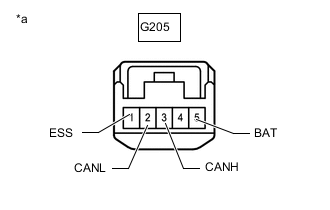
*a Front view of wire harness connector
(to Certification ECU [Smart Key ECU Assembly])
Disconnect the certification ECU (smart key ECU assembly) connector.
-
Measure the resistance according to the value(s) in the table below.
-
-
TELEMATICS TRANSCEIVER (w/ Telematics Transceiver)
Refer to Terminals of ECU.
-
Disconnect the cable from the negative (-) battery terminal.
-
*a Front view of wire harness connector
(to Telematics Transceiver)
Disconnect the Telematics Transceiver connector.
-
Measure the resistance according to the value(s) in the table below.
-
-
REAR TELEVISION CAMERA ASSEMBLY (w/ Multi-terrain Monitor System)
Refer to Terminals of ECU.
-
Disconnect the cable from the negative (-) battery terminal.
-
Disconnect the rear television camera assembly connector.
*A w/o Tire Carrier *B w/ Tire Carrier *a Front view of wire harness connector
(to Rear Television Camera Assembly)
*b Front view of DLC3 -
Measure the resistance according to the value(s) in the table below.
-
-
DRIVING SUPPORT ECU ASSEMBLY (w/ Pre-crash Safety System)
Refer to Terminals of ECU.
-
Disconnect the cable from the negative (-) battery terminal.
-
Disconnect the driving support ECU assembly connector.
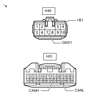
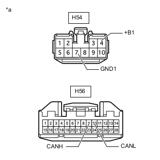
*a Front view of wire harness connector
(to Driving Support ECU Assembly)
*b Front view of DLC3 -
Measure the resistance according to the value(s) in the table below.
-
-
PARKING ASSIST ECU (w/ Parking Assist Monitor System)
Refer to Terminals of ECU.
-
Disconnect the cable from the negative (-) battery terminal.
-
*a Rear view of wire harness connector
(to Parking Assist ECU)
Disconnect the parking assist ECU connectors.
-
Measure the resistance according to the value(s) in the table below.
-
-
CLEARANCE WARNING ECU ASSEMBLY (w/ TOYOTA Parking Assist-sensor System [w/ Multi-display])
Refer to Terminals of ECU.
-
Disconnect the cable from the negative (-) battery terminal.
-
Disconnect the clearance warning ECU assembly connector.
*A for 8 Sensor Type *B for 4 Sensor Type *a Front view of wire harness connector
(to Clearance Warning ECU Assembly)
*b Front view of DLC3 -
Measure the resistance according to the value(s) in the table below.
-
-
STABILIZER CONTROL ECU (w/ Kinetic Dynamic Suspension System)
Refer to Terminals of ECU.
-
Disconnect the cable from the negative (-) battery terminal.
-
Disconnect the stabilizer control ECU connector.
*a Front view of wire harness connector
(to Stabilizer Control ECU)
*b Front view of DLC3 -
Measure the resistance according to the value(s) in the table below.
-
-
NO. 1 HEADLIGHT ECU SUB-ASSEMBLY LH (for LED Headlight)
Refer to Terminals of ECU.
-
Disconnect the cable from the negative (-) battery terminal.
-
*a Front view of wire harness connector
(to No. 1 Headlight ECU Sub-assembly LH)
*b Front view of DLC3 Disconnect the No. 1 headlight ECU sub-assembly LH connector.
-
Measure the resistance according to the value(s) in the table below.
-
-
BUS BUFFER ECU (w/ Bus Buffer ECU)
-
Disconnect the cable from the negative (-) battery terminal.
-
*a Front view of wire harness connector
(to Bus Buffer ECU)
*b Front view of DLC3 Measure the resistance according to the value(s) in the table below.
-