METER / GAUGE SYSTEM Engine Coolant Temperature Receiver Gauge Malfunction
DESCRIPTION
In this circuit, the meter CPU receives engine coolant temperature signals from the ECM. The meter CPU displays engine coolant temperature that is calculated based on the data received from the ECM.
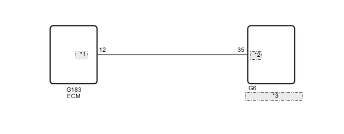
WIRING DIAGRAM
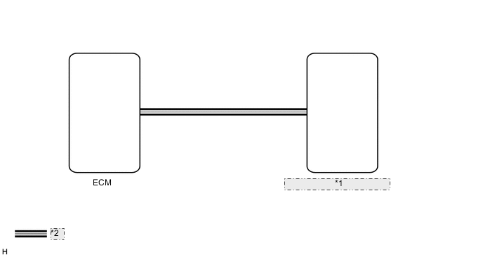
| *1 | Combination Meter Assembly |
| *2 | CAN Communication Line |
| *1 | THWO |
| *2 | TEMP |
| *3 | Combination Meter Assembly |
CAUTION / NOTICE / HINT
Tech Tips
If there is an open or short in the engine coolant temperature sensor circuit, the ECM stores the DTCs. Troubleshoot the SFI System*1 or ECD System*2.
-
*1: for Gasoline Engine
-
*2: for Diesel Engine
-
for 1GR-FE: See page
-
for 2TR-FE: See page
-
for 1KD-FTV: See page
-
for 1GD-FTV: Click here
-
for 1GD-FTV w/ Urea SCR System: See page
-
for 5L-E: See page
PROCEDURE
-
CHECK ENGINE TYPE
-
Check the engine type.
Result Result Proceed to except 5L-E A for 5L-E B
B 
PERFORM ACTIVE TEST USING GTS (WATER TEMPERATURE METER OPERATION) Click here
A 
-
-
CHECK CAN COMMUNICATION SYSTEM
-
Check if a CAN communication DTC is output.
-
for LHD with Entry and Start System Click here.
-
for LHD without Entry and Start System Click here.
-
for RHD with Entry and Start System Click here.
-
for RHD without Entry and Start System Click here.
Result Result Proceed to CAN communication DTC is not output. A CAN communication DTC is output. (for LHD with Entry and Start System) B CAN communication DTC is output. (for LHD without Entry and Start System) C CAN communication DTC is output. (for RHD with Entry and Start System) D CAN communication DTC is output. (for RHD without Entry and Start System) E
-
B 
GO TO CAN COMMUNICATION SYSTEM Click here
C
GO TO CAN COMMUNICATION SYSTEM Click here
D
GO TO CAN COMMUNICATION SYSTEM Click here
E
GO TO CAN COMMUNICATION SYSTEM Click here
A
-
-
PERFORM ACTIVE TEST USING GTS (WATER TEMPERATURE METER OPERATION)
-
Using the GTS, perform the Active Test Click here.
Combination Meter Tester Display Measurement Item/Range Normal Condition Diagnostic Note Water Temperature Meter Operation Engine coolant temperature receiver gauge OFF, 45, 60, 70, 80, Middle, 110, 120, 127 - OK Engine coolant temperature receiver gauge indication is normal.
NG
REPLACE COMBINATION METER ASSEMBLY Click here
OK
-
-
READ VALUE USING GTS (COOLANT TEMPERATURE)
-
Using the GTS, read the Data List Click here.
Combination Meter Tester Display Measurement Item/Range Normal Condition Diagnostic Note Coolant Temperature Engine coolant temperature/Min.: 0°C (0°F), Max.: 127.5°C (261.5°F) 75 to 100°C (167 to 212°F): After warming up the engine - OK Coolant temperature displayed on the GTS is between 75°C (167°F) and 100°C (212°F) after warming up.
OK
REPLACE COMBINATION METER ASSEMBLY Click here
NG
-
-
READ VALUE USING GTS (COOLANT TEMP)
-
Using the GTS, read the Data List Click here.
Engine and ECT Tester Display Measurement Item/Range Normal Condition Diagnostic Note Coolant Temp Engine coolant temperature/Min.: -40°C (-40°F), Max: 215°C (419°F) 75 to 100°C (167 to 212°F): After warming up the engine - OK Engine coolant temperature value displayed on the GTS is almost the same as actual engine coolant temperature. Result Result Proceed to OK A NG (for 1GR-FE) B NG (for 2TR-FE) C NG (for 1KD-FTV) D NG (for 1GD-FTV) E
A
REPLACE COMBINATION METER ASSEMBLY Click here
B
REPLACE ECM Click here
C
REPLACE ECM Click here
D
REPLACE ECM Click here
E
REPLACE ECM Click here
-
-
PERFORM ACTIVE TEST USING GTS (WATER TEMPERATURE METER OPERATION)
-
Using the GTS, perform the Active Test Click here.
Combination Meter Tester Display Measurement Item/Range Normal Condition Diagnostic Note Water Temperature Meter Operation Engine coolant temperature receiver gauge LOW, 60, 70, 80, Normal, 110, 120, HIGH - OK Engine coolant temperature receiver gauge indication is normal.
NG
REPLACE COMBINATION METER ASSEMBLY Click here
OK
-
-
READ VALUE USING GTS (COOLANT TEMPERATURE)
-
Using the GTS, read the Data List Click here.
Combination Meter Tester Display Measurement Item/Range Normal Condition Diagnostic Note Coolant Temperature Engine coolant temperature/Min.: 0°C (0°F), Max.: 127.5°C (261.5°F) 75 to 100°C (167 to 212°F): After warming up the engine - OK Coolant temperature displayed on the GTS is between 75°C (167°F) and 100°C (212°F) after warming up.
OK
REPLACE COMBINATION METER ASSEMBLY Click here
NG
-
-
READ VALUE USING GTS (COOLANT TEMP)
-
Using the GTS, read the Data List Click here.
Engine and ECT Tester Display Measurement Item/Range Normal Condition Diagnostic Note Coolant Temp Engine coolant temperature/Min.: -40°C (-40°F), Max: 215°C (419°F) 75 to 100°C (167 to 212°F): After warming up the engine - OK Engine coolant temperature value displayed on the GTS is almost the same as actual engine coolant temperature.
NG
REPLACE ECM Click here
OK
-
-
CHECK HARNESS AND CONNECTOR (COMBINATION METER ASSEMBLY - ECM)
-
Disconnect the G6 combination meter assembly connector.
-
Disconnect the G183 ECM connector.
-
Measure the resistance according to the value(s) in the table below.
Standard Resistance Tester Connection Condition Specified Condition G6-35 (TEMP) - G183-12 (THWO) Always Below 1 Ω G6-35 (TEMP) or G183-12 (THWO) - Body ground Always 10 kΩ or higher
NG
REPAIR OR REPLACE HARNESS OR CONNECTOR
OK
-
-
CHECK COMBINATION METER ASSEMBLY
-
Replace the combination meter assembly Click here.
-
Check that the operation of the engine coolant temperature receiver gauge returns to normal.
OK The operation of the engine coolant temperature receiver gauge returns to normal.
OK
END (COMBINATION METER ASSEMBLY IS DEFECTIVE)
NG
REPLACE ECM Click here
-