METER / GAUGE SYSTEM Fuel Receiver Gauge Malfunction
DESCRIPTION
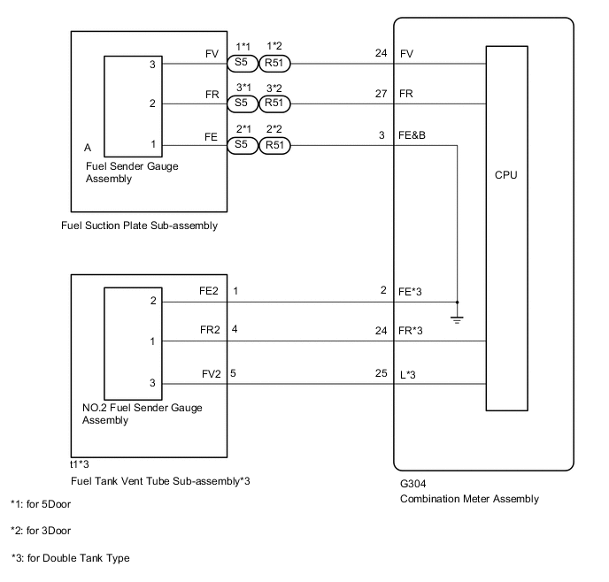
The combination meter assembly uses the fuel injection volume signal from the ECM, fuel sender gauge assembly to detect the amount of fuel remaining in the fuel tank assembly. Each gauge assembly has a variable resistor whose resistance changes according to the amount of fuel remaining. The gauge assemblies receive voltage from the combination meter assembly and change the voltage based on the resistance that changes according to the amount of fuel remaining in the fuel tank assembly. The combination meter assembly receives a fuel injection volume signal from the ECM and detects the voltage between each variable resistor and each resistor in the combination meter assembly, and operates the fuel receiver gauge.
CAUTION / NOTICE / HINT
Note
When replacing the combination meter assembly, always replace it with a new one. If a combination meter assembly which was installed to another vehicle is used, the information stored in it will not match the information from the vehicle and a DTC may be stored.
Tech Tips
The fuel level warning light will come on when the fuel level is below 9.96 liters (10.5 US qts, 8.8 Imp. qts).
WIRING DIAGRAM
Figure 1. except 5L-E
PROCEDURE
-
CHECK FOR DTC
-
Clear the DTCs.
-
Recheck for DTCs and check that no DTCs are output.
Result Result Proceed to DTC B1500 and B1501 is not output A DTC B1500 is output B DTC B1501 is output C
B 
GO TO DTC B1500 Click here
C
GO TO DTC B1501 Click here
A 
-
-
PERFORM ACTIVE TEST USING GTS (FUEL METER OPERATION)
-
Using the GTS, perform the Active Test.
Combination Meter Tester Display Test Part Control Range Diagnostic Note Fuel Meter Operation Fuel receiver gauge OFF, Sender, Empty, Warning, 1/ 4, 1/2, 3/4, Full or Sender F - OK Fuel receiver gauge indication is normal. Result Proceed to OK NG
NG
REPLACE COMBINATION METER ASSEMBLY Click here
OK
-
-
CHECK VEHICLE TYPE
-
Check the vehicle type.
Result Result Proceed to except 5L-E (for Single Tank Type) A except 5L-E (for Double Tank Type) B for 5L-E (for Single Tank Type) C for 5L-E (for Double Tank Type) D
B 
CHECK FUEL SENDER GAUGE ASSEMBLY (POWER SOURCE) Click here
C
CHECK HARNESS AND CONNECTOR (FUEL GAUGE CIRCUIT) Click here
D
CHECK HARNESS AND CONNECTOR (FUEL GAUGE CIRCUIT) Click here
A
-
-
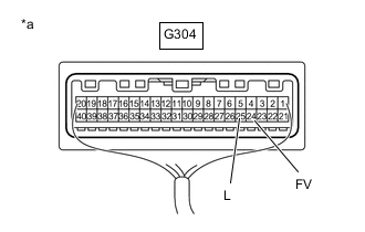
CHECK FUEL SENDER GAUGE ASSEMBLY (POWER SOURCE)

*a Component with harness connected
(Combination Meter Assembly)
-
Measure the voltage according to the value(s) in the table below.
Standard Voltage Tester Connection Switch Condition Specified Condition G304-24 (FV) - Body ground Engine switch on (IG) 4.5 to 5.5 V Result Proceed to OK NG
NG
REPLACE COMBINATION METER ASSEMBLY Click here
OK
-
-
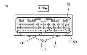
CHECK FUEL SENDER GAUGE ASSEMBLY
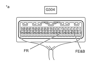
*a Component with harness connected
(Combination Meter Assembly)
-
Measure the voltage according to the value(s) in the table below.
Standard Voltage Tester Connection Switch Condition Specified Condition G304-27 (FR) - G304-3 (FE&B) Engine switch on (IG) 0.2 to 4.7 V Result Proceed to OK NG
OK
REPLACE COMBINATION METER ASSEMBLY Click here
NG
-
-
CHECK HARNESS AND CONNECTOR (FUEL SUCTION PLATE SUB-ASSEMBLY - COMBINATION METER ASSEMBLY)
-
Disconnect the S5*1 or R51*2 fuel suction plate sub-assembly connector.
-
*1: for 5Door
-
*2: for 3Door
-
-
Disconnect the G304 combination meter assembly connector.
-
Measure the resistance according to the value(s) in the table below.
Standard Resistance (for 5Door) Tester Connection Condition Specified Condition S5-3 (FR) - G304-27 (FR) Always Below 1 Ω S5-2 (FE) - G304-3 (FE&B) Always Below 1 Ω S5-1 (FV) - G304-24 (FV) Always Below 1 Ω G304-27 (FR) - Body ground Always 10 kΩ or higher G304-3 (FE&B) - Body ground Always 10 kΩ or higher G304-24 (FV) - Body ground Always 10 kΩ or higher Standard Resistance (for 3Door) Tester Connection Condition Specified Condition R51-3 (FR) - G304-27 (FR) Always Below 1 Ω R51-2 (FE) - G304-3 (FE&B) Always Below 1 Ω R51-1 (FV) - G304-24 (FV) Always Below 1 Ω G304-27 (FR) - Body ground Always 10 kΩ or higher G304-3 (FE&B) - Body ground Always 10 kΩ or higher G304-24 (FV) - Body ground Always 10 kΩ or higher Result Proceed to OK NG
NG
REPAIR OR REPLACE HARNESS OR CONNECTOR
OK
-
-
INSPECT FUEL SENDER GAUGE ASSEMBLY
-
Remove the fuel sender gauge assembly.
-
for Single Tank Type (for 1GR-FE)
-
for Single Tank Type (for 1KD-FTV)
-
for Single Tank Type (for 1GD-FTV)
-
for Single Tank Type (for 2TR-FE)
-
for Double Tank Type (for 1GR-FE)
-
for Double Tank Type (for 1KD-FTV)
-
for Double Tank Type (for 1GD-FTV)
-
for Double Tank Type (for 2TR-FE)
-
-
Inspect the fuel sender gauge assembly.
-
for Single Tank Type (for 1GR-FE)
-
for Single Tank Type (for 1KD-FTV)
-
for Single Tank Type (for 1GD-FTV)
-
for Single Tank Type (for 2TR-FE)
-
for Double Tank Type (for 1GR-FE)
-
for Double Tank Type (for 1KD-FTV)
-
for Double Tank Type (for 1GD-FTV)
-
for Double Tank Type (for 2TR-FE)
Result Proceed to OK NG -
NG
REPLACE FUEL SENDER GAUGE ASSEMBLY for Single Tank Type (for 1GR-FE) Click here for Single Tank Type (for 1KD-FTV) Click here for Single Tank Type (for 1GD-FTV) Click here for Single Tank Type (for 2TR-FE) Click here for Double Tank Type (for 1GR-FE) Click here for Double Tank Type (for 1KD-FTV) Click here for Double Tank Type (for 1GD-FTV) Click here for Double Tank Type (for 2TR-FE) Click here
OK
-
-
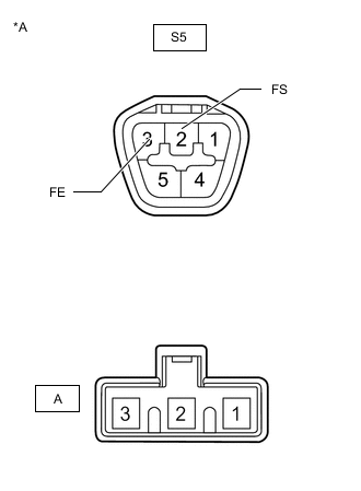
INSPECT FUEL SUCTION PLATE SUB-ASSEMBLY
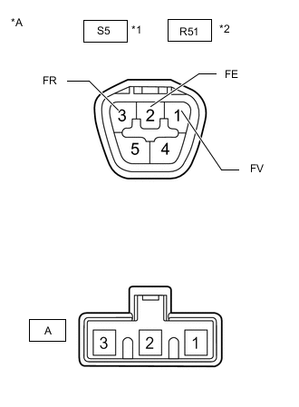
*A Component without harness connected
(Fuel Suction Plate Sub-assembly)
*1 for 5Door *2 for 3Door
-
Measure the resistance according to the value(s) in the table below.
Standard Resistance (for 5Door) Tester Connection Condition Specified Condition S5-1 (FV) - A-3 Always Below 1 Ω S5-2 (FE) - A-2 Always Below 1 Ω S5-3 (FR) - A-1 Always Below 1 Ω Standard Resistance (for 3Door) Tester Connection Condition Specified Condition R51-1 (FV) - A-3 Always Below 1 Ω R51-2 (FE) - A-2 Always Below 1 Ω R51-3 (FR) - A-1 Always Below 1 Ω Result Proceed to OK NG
OK
REPLACE COMBINATION METER ASSEMBLY Click here
NG
REPLACE FUEL SUCTION PLATE SUB-ASSEMBLY for Single Tank Type (for 1GR-FE) Click here for Single Tank Type (for 1KD-FTV) Click here for Single Tank Type (for 1GD-FTV) Click here for Single Tank Type (for 2TR-FE) Click here for Double Tank Type (for 1GR-FE) Click here for Double Tank Type (for 1KD-FTV) Click here for Double Tank Type (for 1GD-FTV) Click here for Double Tank Type (for 2TR-FE) Click here
-
-
CHECK FUEL SENDER GAUGE ASSEMBLY (POWER SOURCE)
*a Component with harness connected
(Combination Meter Assembly)
-
Measure the voltage according to the value(s) in the table below.
Standard Voltage Tester Connection Switch Condition Specified Condition G304-24 (FV) - Body ground Engine switch on (IG) 4.5 to 5.5 V G304-25 (L) - Body ground Engine switch on (IG) 4.5 to 5.5 V Result Proceed to OK NG
NG
REPLACE COMBINATION METER ASSEMBLY Click here
OK
-
-
CHECK FUEL SENDER GAUGE ASSEMBLY
*a Component with harness connected
(Combination Meter Assembly)
-
Measure the voltage according to the value(s) in the table below.
Standard Voltage Tester Connection Switch Condition Specified Condition G304-27 (FR) - G304-3 (FE&B) Engine switch on (IG) 0.2 to 4.7 V G304-26 (FR) - G304-2 (FE) Engine switch on (IG) 0.2 to 4.7 V Result Proceed to OK NG
OK
REPLACE COMBINATION METER ASSEMBLY Click here
NG
-
-
CHECK HARNESS AND CONNECTOR (FUEL SUCTION PLATE SUB-ASSEMBLY - COMBINATION METER ASSEMBLY)
-
Disconnect the S5*1 or R51*2 fuel suction plate sub-assembly connector.
-
*1: for 5Door
-
*2: for 3Door
-
-
Disconnect the G304 combination meter assembly connector.
-
Measure the resistance according to the value(s) in the table below.
Standard Resistance (for 5Door) Tester Connection Condition Specified Condition S5-3 (FR) - G304-27 (FR) Always Below 1 Ω S5-2 (FE) - G304-3 (FE&B) Always Below 1 Ω S5-1 (FV) - G304-24 (FV) Always Below 1 Ω G304-27 (FR) - Body ground Always 10 kΩ or higher G304-3 (FE&B) - Body ground Always 10 kΩ or higher G304-24 (FV) - Body ground Always 10 kΩ or higher Standard Resistance (for 3Door) Tester Connection Condition Specified Condition R51-3 (FR) - G304-27 (FR) Always Below 1 Ω R51-2 (FE) - G304-3 (FE&B) Always Below 1 Ω R51-1 (FV) - G304-24 (FV) Always Below 1 Ω G304-27 (FR) - Body ground Always 10 kΩ or higher G304-3 (FE&B) - Body ground Always 10 kΩ or higher G304-24 (FV) - Body ground Always 10 kΩ or higher Result Proceed to OK NG
NG
REPAIR OR REPLACE HARNESS OR CONNECTOR
OK
-
-
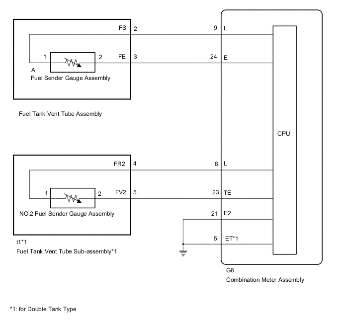
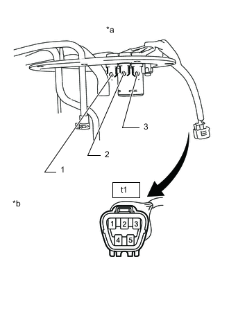
CHECK HARNESS AND CONNECTOR (FUEL TANK VENT TUBE ASSEMBLY - COMBINATION METER ASSEMBLY)
-
Disconnect the t1 fuel tank vent tube assembly connector.
-
Disconnect the G304 combination meter assembly connector.
-
Measure the resistance according to the value(s) in the table below.
Standard Resistance Tester Connection Condition Specified Condition t1-4 (FR2) - G304-26 (FR) Always Below 1 Ω 2t1-1 (FE) - G304-3 (FE) Always Below 1 Ω t1-5 (FV2) - G304-25 (L) Always Below 1 Ω G304-26 (FR) - Body ground Always 10 kΩ or higher G304-2 (FE) - Body ground Always 10 kΩ or higher G304-25 (L) - Body ground Always 10 kΩ or higher Result Proceed to OK NG
NG
REPAIR OR REPLACE HARNESS OR CONNECTOR
OK
-
-
INSPECT FUEL SENDER GAGE ASSEMBLY
-
Remove the fuel sender gauge assembly.
-
for Single Tank Type (for 1GR-FE)
-
for Single Tank Type (for 1KD-FTV)
-
for Single Tank Type (for 1GD-FTV)
-
for Single Tank Type (for 2TR-FE)
-
for Double Tank Type (for 1GR-FE)
-
for Double Tank Type (for 1KD-FTV)
-
for Double Tank Type (for 1GD-FTV)
-
for Double Tank Type (for 2TR-FE)
-
-
Inspect the fuel sender gauge assembly.
-
for Single Tank Type (for 1GR-FE)
-
for Single Tank Type (for 1KD-FTV)
-
for Single Tank Type (for 1GD-FTV)
-
for Single Tank Type (for 2TR-FE)
-
for Double Tank Type (for 1GR-FE)
-
for Double Tank Type (for 1KD-FTV)
-
for Double Tank Type (for 1GD-FTV)
-
for Double Tank Type (for 2TR-FE)
Result Proceed to OK NG -
NG
REPLACE FUEL SENDER GAUGE ASSEMBLY for Single Tank Type (for 1GR-FE) Click here for Single Tank Type (for 1KD-FTV) Click here for Single Tank Type (for 1GD-FTV) Click here for Single Tank Type (for 2TR-FE) Click here for Double Tank Type (for 1GR-FE) Click here for Double Tank Type (for 1KD-FTV) Click here for Double Tank Type (for 1GD-FTV) Click here for Double Tank Type (for 2TR-FE) Click here
OK
-
-
INSPECT FUEL SENDER GAGE ASSEMBLY NO.2
-
Remove the fuel sender gauge assembly.
-
for Double Tank Type (for 1GR-FE)
-
for Double Tank Type (for 1KD-FTV)
-
for Double Tank Type (for 1GD-FTV)
-
for Double Tank Type (for 2TR-FE)
-
-
Inspect the fuel sender gauge assembly.
-
for Double Tank Type (for 1GR-FE)
-
for Double Tank Type (for 1KD-FTV)
-
for Double Tank Type (for 1GD-FTV)
-
for Double Tank Type (for 2TR-FE)
Result Proceed to OK NG -
NG
REPLACE FUEL SENDER GAGE ASSEMBLY NO.2 for Double Tank Type (for 1GR-FE) Click here for Double Tank Type (for 1KD-FTV) Click here for Double Tank Type (for 1GD-FTV) Click here for Double Tank Type (for 2TR-FE) Click here
OK
-
-
INSPECT FUEL SUCTION PLATE SUB-ASSEMBLY
*A Component without harness connected
(Fuel Suction Plate Sub-assembly)
*1 for 5Door *2 for 3Door
-
Measure the resistance according to the value(s) in the table below.
Standard Resistance (for 5Door) Tester Connection Condition Specified Condition S5-1 (FV) - A-3 Always Below 1 Ω S5-2 (FE) - A-2 Always Below 1 Ω S5-3 (FR) - A-1 Always Below 1 Ω Standard Resistance (for 3Door) Tester Connection Condition Specified Condition R51-1 (FV) - A-3 Always Below 1 Ω R51-2 (FE) - A-2 Always Below 1 Ω R51-3 (FR) - A-1 Always Below 1 Ω Result Proceed to OK NG
NG
REPLACE FUEL SUCTION PLATE SUB-ASSEMBLY for Single Tank Type (for 1GR-FE) Click here for Single Tank Type (for 1KD-FTV) Click here for Single Tank Type (for 1GD-FTV) Click here for Single Tank Type (for 2TR-FE) Click here for Double Tank Type (for 1GR-FE) Click here for Double Tank Type (for 1KD-FTV) Click here for Double Tank Type (for 1GD-FTV) Click here for Double Tank Type (for 2TR-FE) Click here
OK
-
-
INSPECT FUEL TANK VENT TUBE ASSEMBLY
*a Fuel Tank Vent Tube Assembly *b Component without harness connected
(Fuel Tank Vent Tube Assembly)
-
Measure the resistance according to the value(s) in the table below.
Standard Resistance Tester Connection Condition Specified Condition t1-1 (FE2) - 2 Always Below 1 Ω t1-4 (FR2) - 1 Always Below 1 Ω t1-5 (FV2) - 3 Always Below 1 Ω Result Proceed to OK NG
OK
REPLACE COMBINATION METER ASSEMBLY Click here
NG
REPLACE FUEL TANK VENT TUBE ASSEMBLY for Double Tank Type (for 1GR-FE) Click here for Double Tank Type (for 1KD-FTV) Click here for Double Tank Type (for 1GD-FTV) Click here for Double Tank Type (for 2TR-FE) Click here
-
-
CHECK HARNESS AND CONNECTOR (FUEL GAUGE CIRCUIT)
-
Disconnect the G6 combination meter assembly connector.
-
Disconnect the S5 fuel sender gauge assembly connector.
-
Measure the resistance according to the value(s) in the table below.
Standard Resistance Tester Connection Condition Specified Condition G6-9 (L) - S5-2 (FS) Always Below 1 Ω G6-24 (E) - S5-3 (FE) Always Below 1 Ω G6-21 (E2) - Body ground Always Below 1 Ω G6-16 (L) or S5-2 (FS) - Body ground Always 10 kΩ or higher G6-15 (E) or S5-3 (FE) - Body ground Always 10 kΩ or higher Result Proceed to OK NG
NG
REPAIR OR REPLACE HARNESS OR CONNECTOR
OK
-
-
INSPECT FUEL TANK VENT TUBE ASSEMBLY
-
Remove the fuel sender gauge assembly.
-
Inspect the fuel sender gauge assembly.
Result Proceed to OK NG
NG
REPLACE FUEL SENDER GAUGE ASSEMBLY Click here
OK
-
-
INSPECT FUEL TANK VENT TUBE ASSEMBLY
*a Component without harness connected
(Fuel Tank Vent Tube Assembly)
-
Measure the resistance according to the value(s) in the table below.
Standard Resistance Tester Connection Condition Specified Condition S5-2 (FS) - A-2 Always Below 1 Ω S5-3 (FE) - A-1 Always Below 1 Ω Result Proceed to OK NG
OK
REPLACE COMBINATION METER ASSEMBLY Click here
NG
REPLACE FUEL TANK VENT TUBE ASSEMBLY Click here
-
-
CHECK HARNESS AND CONNECTOR (FUEL GAUGE CIRCUIT)
-
Disconnect the G6 combination meter assembly connector.
-
Disconnect the S5 fuel sender gauge assembly connector.
-
Measure the resistance according to the value(s) in the table below.
Standard Resistance Tester Connection Condition Specified Condition G6-9 (L) - S5-2 (FS) Always Below 1 Ω G6-24 (E) - S5-3 (FE) Always Below 1 Ω G6-21 (E2) - Body ground Always Below 1 Ω G6-16 (L) or S5-2 (FS) - Body ground Always 10 kΩ or higher G6-15 (E) or S5-3 (FE) - Body ground Always 10 kΩ or higher Result Proceed to OK NG
NG
REPAIR OR REPLACE HARNESS OR CONNECTOR
OK
-
-
CHECK HARNESS AND CONNECTOR (FUEL GAUGE CIRCUIT)
-
Disconnect the G6 combination meter assembly connector.
-
Disconnect the t1 fuel sender gauge assembly connector.
-
Measure the resistance according to the value(s) in the table below.
Standard Resistance Tester Connection Condition Specified Condition G6-8 (L) - t1-4 (FR2) Always Below 1 Ω G6-23 (FE) - t1-5 (FV2) Always Below 1 Ω G6-5 (ET) - Body ground Always Below 1 Ω G6-8 (L) or t1-4 (FR2) - Body ground Always 10 kΩ or higher G6-23 (FE) or t1-5 (FV2) - Body ground Always 10 kΩ or higher Result Proceed to OK NG
NG
REPAIR OR REPLACE HARNESS OR CONNECTOR
OK
-
-
INSPECT FUEL SENDER GAGE ASSEMBLY
-
Remove the fuel sender gauge assembly.
-
Inspect the fuel sender gauge assembly.
Result Proceed to OK NG
NG
REPLACE FUEL SENDER GAUGE ASSEMBLY Click here
OK
-
-
INSPECT FUEL SENDER GAGE ASSEMBLY NO.2
-
Remove the fuel sender gauge assembly.
-
Inspect the fuel sender gauge assembly.
Result Proceed to OK NG
NG
REPLACE FUEL SENDER GAUGE ASSEMBLY Click here
OK
-
-
INSPECT FUEL TANK VENT TUBE ASSEMBLY
*a Component without harness connected
(Fuel Tank Vent Tube Assembly)
-
Measure the resistance according to the value(s) in the table below.
Standard Resistance Tester Connection Condition Specified Condition S5-2 (FS) - A-2 Always Below 1 Ω S5-3 (FE) - A-1 Always Below 1 Ω Result Proceed to OK NG
NG
REPLACE FUEL TANK VENT TUBE ASSEMBLY Click here
OK
-
-
INSPECT FUEL TANK VENT TUBE ASSEMBLY
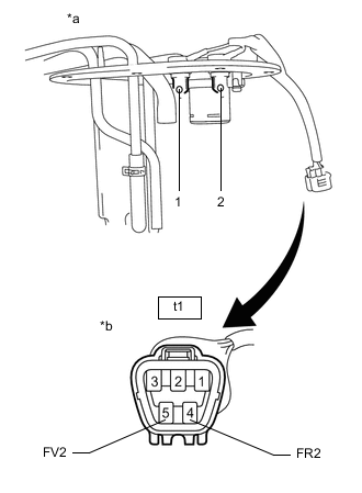
*a Fuel Tank Vent Tube Assembly *b Component without harness connected
(Fuel Tank Vent Tube Assembly)
-
Measure the resistance according to the value(s) in the table below.
Standard Resistance Tester Connection Condition Specified Condition t1-4 (FR2) - 1 Always Below 1 Ω t1-5 (FV2) - 2 Always Below 1 Ω Result Proceed to OK NG
OK
REPLACE COMBINATION METER ASSEMBLY Click here
NG
REPLACE FUEL TANK VENT TUBE ASSEMBLY Click here
-