METER / GAUGE SYSTEM Tachometer Malfunction
DESCRIPTION
In this circuit, the meter CPU receives engine speed signals from the ECM. The meter CPU displays the engine speed calculated based on the data received from the ECM.
WIRING DIAGRAM
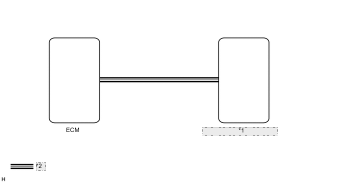
| *1 | Combination Meter Assembly |
| *2 | CAN Communication Line |
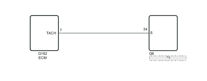
| *1 | Combination Meter Assembly |
PROCEDURE
-
CHECK ENGINE TYPE
-
Check the engine type.
Result Result Proceed to except 5L-E A for 5L-E B
B 
PERFORM ACTIVE TEST USING GTS (TACHO METER OPERATION) Click here
A 
-
-
CHECK CAN COMMUNICATION SYSTEM
-
Check if a CAN communication DTC is output.
-
for LHD with Entry and Start System Click here.
-
for LHD without Entry and Start System Click here.
-
for RHD with Entry and Start System Click here.
-
for RHD without Entry and Start System Click here.
Result Result Proceed to CAN communication DTC is not output. A CAN communication DTC is output. (for LHD, with Entry and Start System) B CAN communication DTC is output. (for LHD, without Entry and Start System) C CAN communication DTC is output. (for RHD, with Entry and Start System) D CAN communication DTC is output. (for RHD, without Entry and Start System) E
-
B 
GO TO CAN COMMUNICATION SYSTEM Click here
C
GO TO CAN COMMUNICATION SYSTEM Click here
D
GO TO CAN COMMUNICATION SYSTEM Click here
E
GO TO CAN COMMUNICATION SYSTEM Click here
A
-
-
PERFORM ACTIVE TEST USING GTS (TACHO METER OPERATION)
-
Using the GTS, perform the Active Test Click here.
Combination Meter Tester Display Test Part Control Range Diagnostic Note Tacho Meter Operation Tachometer OFF, 0, 1000, 2000, 3000, 4000, 5000, 6000 or 7000* (rpm) -
-
*: for 1GR-FE, 2TR-FE
OK Tachometer indication is normal.
-
NG
GO TO CAN COMMUNICATION SYSTEM Click here
OK
-
-
READ VALUE USING GTS (ENGINE RPM)
-
Using the GTS, read the Data List Click here.
Combination Meter Tester Display Measurement Item/Range Normal Condition Diagnostic Note Engine Rpm Engine speed/Min.: 0 rpm, Max.: 12750 rpm 600 to 700 rpm (When idling) If the data received from the ECM exceeds the range that can be displayed on the meter, the meter continues to display the maximum value of the range. OK Engine speed displayed on the intelligent tester is almost the same as the tachometer indication. -
Record the engine speed displayed on the intelligent tester.
Tech Tips
Check the engine speed when the engine is fully warmed up and the air conditioning and all electrical accessories are off.
OK
REPLACE COMBINATION METER ASSEMBLY Click here
NG
-
-
READ VALUE USING GTS (ENGINE SPEED)
-
Using the GTS, read the Data List Click here.
Engine and ECT Tester Display Measurement Item/Range Normal Condition Diagnostic Note Engine Speed Engine speed/Min.: 0 rpm, Max.: 16383 rpm 600 to 700 rpm (When idling) - OK Engine speed displayed on GTS is almost same as actual engine speed. Result Result Proceed to OK A NG (for Gasoline Engine) B NG (for Diesel Engine) C Tech Tips
-
for 1GR-FE:
If it is necessary to refer to the SFI system, refer to the following procedures (See page ).
-
for 2TR-FE:
If it is necessary to refer to the SFI system, refer to the following procedures (See page ).
-
for 1KD-FTV:
If it is necessary to refer to the ECD system, refer to the following procedures (See page ).
-
for 1GD-FTV
If it is necessary to refer to the ECD system, refer to the following procedures Click here.
-
for 1GD-FTV, w/ Urea SCR System:
If it is necessary to refer to the ECD system, refer to the following procedures (See page ).
-
B
GO TO SFI SYSTEM
C
GO TO ECD SYSTEM
A
-
-
CHECK ECM
-
Replace the ECM with a new or normally functioning one.
-
for 1GR-FE: Click here
-
for 2TR-FE: Click here
-
for 1KD-FTV: Click here
-
for 1GD-FTV: Click here
-
-
Check that the operation of the tachometer returns to normal.
OK The operation of the tachometer returns to normal.
OK
END (ECM IS DEFECTIVE)
NG
REPLACE COMBINATION METER ASSEMBLY Click here
-
-
PERFORM ACTIVE TEST USING GTS (TACHO METER OPERATION)
-
Using the GTS, perform the Active Test Click here.
Combination Meter Tester Display Test Part Control Range Diagnostic Note Tacho Meter Operation Tachometer OFF, 0, 1000, 2000, 3000, 4000, 5000, 6000 or 7000* (rpm) -
-
*: for 1GR-FE, 2TR-FE
OK Tachometer indication is normal.
-
NG
REPLACE COMBINATION METER ASSEMBLY Click here
OK
-
-
CHECK COMBINATION METER ASSEMBLY (ENGINE SPEED SIGNAL)
-
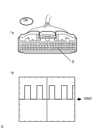
Text in Illustration *a Front view of wire harness connector
(to Combination Meter Assembly)
*b Speed Signal Waveform Remove the combination meter assembly with the connector(s) still connected Click here.
-
Check the signal waveform according to the condition(s) in the table below.
Measurement Condition Item Content Tester Connection G6-34 (S) - Body ground Tool Setting 5 V/DIV, 20 ms./DIV Vehicle Condition Idling with warm engine Tech Tips
As the engine speed increases, the wavelength shortens.
OK The waveform displayed is as shown in the illustration.
OK
REPLACE COMBINATION METER ASSEMBLY Click here
NG
-
-
CHECK HARNESS AND CONNECTOR (COMBINATION METER ASSEMBLY - ECM)
-
Disconnect the G6 combination meter assembly connector.
-
Disconnect the G182 ECM connector.
-
Measure the resistance according to the value(s) in the table below.
Standard Resistance Tester Connection Condition Specified Condition G6-34 (S) - G182-7 (TACH) Always Below 1 Ω G6-34 (S) or G182-7 (TACH) - Body ground Always 10 kΩ or higher
NG
REPAIR OR REPLACE HARNESS OR CONNECTOR
OK
-
-
CHECK ECM
-
Replace the ECM with a new or normally functioning one Click here.
-
Check that the operation of the tachometer returns to normal.
OK The operation of the tachometer returns to normal.
OK
END (ECM IS DEFECTIVE)
NG
REPLACE COMBINATION METER ASSEMBLY Click here
-