METER / GAUGE SYSTEM Speedometer Malfunction
DESCRIPTION
The meter CPU receives vehicle speed signals from the skid control ECU via the CAN communication system. The speed sensor detects the wheel speed and sends the appropriate signals to the skid control ECU. The skid control ECU supplies power to the vehicle speed sensor. The skid control ECU detects vehicle speed signals based on the pulses of the voltage.
WIRING DIAGRAM
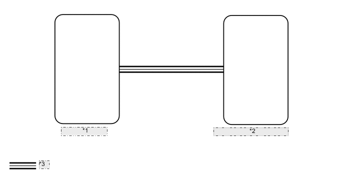
| *1 | Skid Control ECU |
| *2 | Combination Meter Assembly |
| *3 | CAN Communication Line |
CAUTION / NOTICE / HINT
Note
If the vehicle speed is outside the allowable range when tested, perform the on-vehicle inspection Click here.
Tech Tips
Before starting the following inspection, check tire size and tire air pressure.
PROCEDURE
-
CHECK CAN COMMUNICATION SYSTEM
-
Check if a CAN communication DTC is output.
-
w/ Central Gatway ECU Click here.
-
w/o Central Gatway ECU Click here.
Result Result Proceed to CAN communication DTC is not output. A CAN communication DTC is output. (w/ Central Gatway ECU) B CAN communication DTC is output. (w/o Central Gatway ECU) C
-
B 
GO TO CAN COMMUNICATION SYSTEM Click here
C
GO TO CAN COMMUNICATION SYSTEM Click here
A 
-
-
PERFORM ACTIVE TEST USING GTS (SPEED METER OPERATION)
-
Using the GTS, perform the Active Test Click here.
Combination Meter Tester Display Test Part Control Range Diagnostic Note Speed Meter Operation Speedometer
-
OFF, 0, 40, 80, 120, 160 or 200 (km/h) (for km/h)
-
OFF, 0, 40, 80 or , 120 (mph) (for mph)
There is a deviation in the values displayed on the speedometer display (Control range → Speedometer)
-
40 → 41.7 to 46.2
-
80 → 83.4 to 88.4
-
120 → 125.1 to 130.6
-
160 → 166.2 to 173.2
for km/h (except Australia):
-
40 → 40.8 to 45.3
-
80 → 81.6 to 86.6
-
120 → 122.4 to 127.4
-
160 → 163.2 to 168.2
for km/h (for Australia):
-
40 → 42 to 44.5
-
80 → 83.1 to 87.1
for mph:
OK Speedometer indication is normal. -
NG
REPLACE COMBINATION METER ASSEMBLY Click here
OK
-
-
READ VALUE USING GTS (VEHICLE SPEED METER)
-
Using the GTS, read the Data List Click here.
Combination Meter Tester Display Measurement Item/Range Normal Condition Diagnostic Note Vehicle Speed Meter Vehicle speed/Min.: 0 km/h (0 mph), Max.: 255 km/h (158 mph) Almost the same as actual vehicle speed - OK Vehicle speed displayed on the GTS is almost the same as the actual vehicle speed measured using a speedometer tester (calibrated chassis dynamometer).
OK
REPLACE COMBINATION METER ASSEMBLY Click here
NG
-
-
READ VALUE USING GTS (FR/FL/RR/RL WHEEL SPEED)
-
Using the GTS, read the Data List Click here.
ABS/VSC/TRC Tester Display Measurement Item/Range Normal Condition Diagnostic Note FR Wheel Speed Vehicle speed/Min.: 0 km/h (0 mph), Max.: 326 km/h (202 mph) Almost same as actual vehicle speed - FL Wheel Speed Vehicle speed/Min.: 0 km/h (0 mph), Max.: 326 km/h (202 mph) Almost same as actual vehicle speed - RR Wheel Speed Vehicle speed/Min.: 0 km/h (0 mph), Max.: 326 km/h (202 mph) Almost same as actual vehicle speed - RL Wheel Speed Vehicle speed/Min.: 0 km/h (0 mph), Max.: 326 km/h (202 mph) Almost same as actual vehicle speed - OK Vehicle speed displayed on the GTS is almost the same as the actual vehicle speed measured using a speedometer tester (calibrated chassis dynamometer). Result Result Proceed to OK A NG (for Hydraulic Brake Booster) B NG (for 2TR-FE, Vacuum Brake Booster) C NG (for 5L-E, Vacuum Brake Booster) D
B
GO TO VEHICLE STABILITY CONTROL SYSTEM Click here
C
GO TO VEHICLE STABILITY CONTROL SYSTEM Click here
D
GO TO ANTI-LOCK BRAKE SYSTEM Click here
A
-
-
REPLACE SKID CONTROL ECU
-
Replace the skid control ECU with a new or normally functioning one.
-
for LHD Hydraulic Brake Booster Click here.
-
for RHD Hydraulic Brake Booster Click here.
-
for 2TR-FE, 5L-E Click here.
-
-
Check that the operation of the speedometer returns to normal.
OK The operation of the speedometer returns to normal.
OK
END (SKID CONTROL ECU IS DEFECTIVE)
NG
REPLACE COMBINATION METER ASSEMBLY Click here
-