METER / GAUGE SYSTEM, Diagnostic DTC:B1507, B1508
| DTC Code | DTC Name |
|---|---|
| B1507 | Open in Turn Signal Circuit |
| B1508 | Short in Turn Signal / Hazard Flasher Circuit |
DESCRIPTION
| DTC Code | DTC Detection Condition | Trouble Area |
|---|---|---|
| B1507 | Open in turn signal light circuit. |
|
| B1508 | Short in turn signal light circuit or hazard warning light circuit. |
|
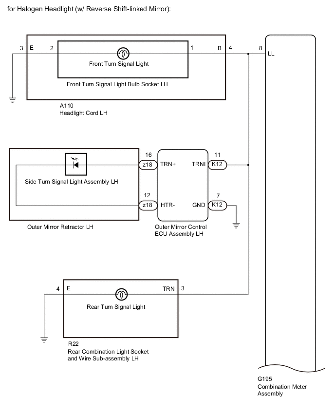
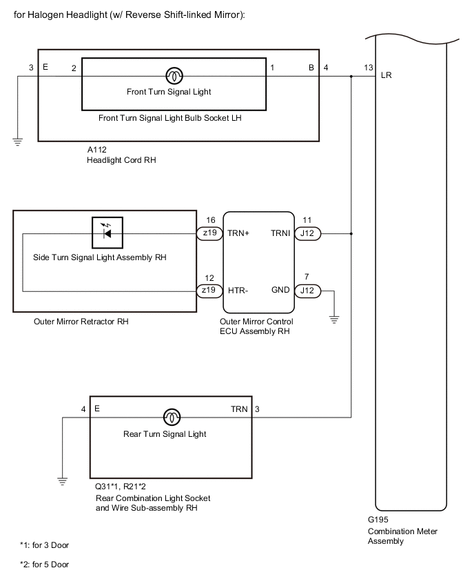
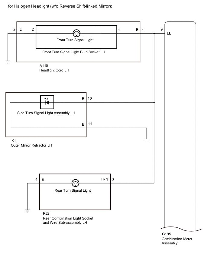
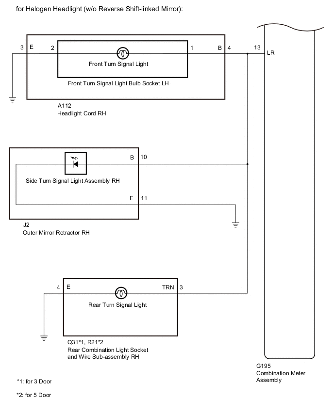
WIRING DIAGRAM
CAUTION / NOTICE / HINT
Note
Inspect the bulbs for circuits related to this system before performing the following inspection procedure.
PROCEDURE
-
CHECK FOR DTC
-
Clear the DTCs.
-
Recheck for DTCs and check that no DTCs are output.
OK B1507 and B1508 are not output. Result Proceed to OK NG
OK 
USE SIMULATION METHOD TO CHECK Click here
NG 
-
-
CHECK VEHICLE TYPE
-
Check the vehicle type.
Result Result Proceed to for Halogen Headlight (w/ Reverse Shift-linked Mirror) A for Halogen Headlight (w/o Reverse Shift-linked Mirror) B for LED Headlight (w/ Reverse Shift-linked Mirror) C for LED Headlight (w/o Reverse Shift-linked Mirror) D
B 
INSPECT LIGHTS Click here
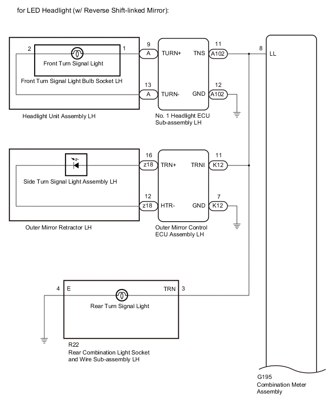
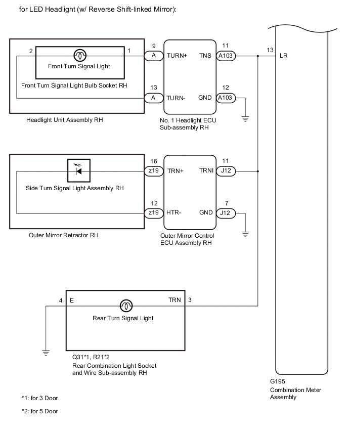
C
INSPECT LIGHTS Click here
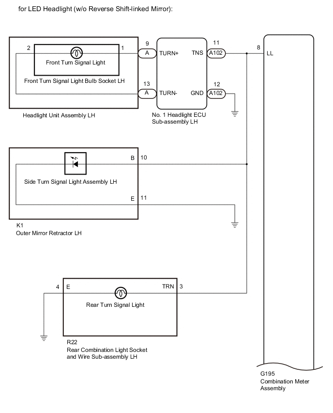
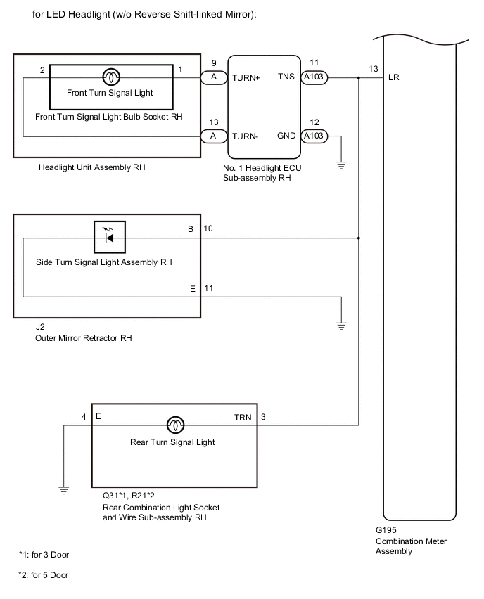
D
INSPECT LIGHTS Click here
A
-
-
INSPECT LIGHTS
-
Inspect the illumination of each turn signal light.
Result Result Proceed to LH side turn signal light does not illuminate. A RH side turn signal light does not illuminate. B
B
CHECK TURN SIGNAL LIGHTS (RH SIDE) Click here
A
-
-
CHECK TURN SIGNAL LIGHTS (LH SIDE)
-
Turn the ignition switch to ON.
-
Set the headlight dimmer switch assembly to the left turn switch position.
-
Check the operation of the turn signal lights (LH side).
Result Result Proceed to Front turn signal light (LH side) does not blink. A Side turn signal light (LH side) does not blink. B Rear turn signal light (LH side) does not blink. C
B
CHECK HARNESS AND CONNECTOR (OUTER MIRROR CONTROL ECU ASSEMBLY LH - COMBINATION METER ASSEMBLY AND BODY GROUND) Click here
C
CHECK HARNESS AND CONNECTOR (REAR COMBINATION LIGHT SOCKET AND WIRE SUB-ASSEMBLY LH - COMBINATION METER ASSEMBLY AND BODY GROUND) Click here
A
-
-
CHECK HARNESS AND CONNECTOR (HEADLIGHT CORD LH - COMBINATION METER ASSEMBLY AND BODY GROUND)
-
Disconnect the G195 combination meter assembly connector.
-
Disconnect the A110 headlight cord LH connector.
-
Disconnect the K12 outer mirror control ECU assembly LH connector.
-
Disconnect the R22 rear combination light socket and wire sub-assembly LH connector.
-
Measure the resistance according to the value(s) in the table below.
Standard Resistance (Check for Open) Tester Connection Condition Specified Condition A110-4 (B) - J195-8 (LL) Always Below 1 Ω A110-3 (E) - Body ground Always Below 1 Ω Standard Resistance (Check for Short) Tester Connection Condition Specified Condition A110-4 (B) - Body ground Always 10 kΩ or higher Result Proceed to OK NG
NG
REPAIR OR REPLACE HARNESS OR CONNECTOR
OK
-
-
INSPECT HEADLIGHT CORD LH
-
Remove the headlight cord LH.
-
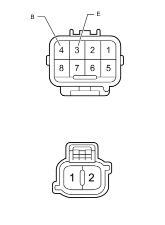
Measure the resistance according to the value(s) in the table below.
Standard Resistance (Check for Open) Tester Connection Condition Specified Condition 4 (B) - 1 Always Below 1 Ω 3 (E) - 2 Always Below 1 Ω Standard Resistance (Check for Short) Tester Connection Condition Specified Condition 4 (B) - 3 (E) Always 10 kΩ or higher Result Proceed to OK NG
NG
REPLACE HEADLIGHT CORD LH Click here
OK
-
-
INSPECT FRONT TURN SIGNAL LIGHT BULB SOCKET LH
-
Remove the front turn signal light bulb socket LH.
-
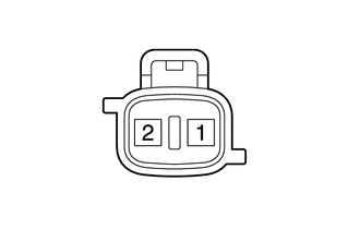
Apply battery voltage and check the operation of the front turn signal light.
OK Battery Connection Specified Condition Positive (+) → 1
Negative (-) → 2
Front turn signal light illuminates Result Proceed to OK NG
OK
REPLACE COMBINATION METER ASSEMBLY Click here
NG
REPLACE FRONT TURN SIGNAL LIGHT BULB SOCKET LH Click here
-
-
CHECK HARNESS AND CONNECTOR (OUTER MIRROR CONTROL ECU ASSEMBLY LH - COMBINATION METER ASSEMBLY AND BODY GROUND)
-
Disconnect the G195 combination meter assembly connector.
-
Disconnect the A110 headlight cord LH connector.
-
Disconnect the K12 outer mirror control ECU assembly LH connector.
-
Disconnect the R22 rear combination light socket and wire sub-assembly LH connector.
-
Measure the resistance according to the value(s) in the table below.
Standard Resistance (Check for Open) Tester Connection Condition Specified Condition K12-11 (TRNI) - G195-8 (LL) Always Below 1 Ω K12-7 (GND) - Body ground Always Below 1 Ω Standard Resistance (Check for Short) Tester Connection Condition Specified Condition K12-11 (TRNI) - Body ground Always 10 kΩ or higher Result Proceed to OK NG
NG
REPAIR OR REPLACE HARNESS OR CONNECTOR
OK
-
-
INSPECT SIDE TURN SIGNAL LIGHT ASSEMBLY LH
-
Remove the side turn signal light assembly LH.
-
Inspect the side turn signal light assembly LH.
Result Proceed to OK NG
NG
REPLACE SIDE TURN SIGNAL LIGHT ASSEMBLY LH Click here
OK
-
-
CHECK OUTER MIRROR RETRACTOR LH
-
Disconnect the z18 outer mirror retractor LH connector.
-
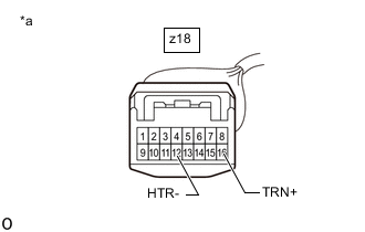
*a Front view of wire harness connector
(to Outer Mirror Control ECU Assembly LH)
Apply battery voltage and check the operation of the side turn signal light.
OK Battery Connection Specified Condition Positive (+) → z18-16 (TRN+)
Negative (-) → z18-12 (HTR-)
Side turn signal light illuminates Result Proceed to OK NG
NG
REPLACE OUTER MIRROR RETRACTOR LH Click here
OK
-
-
INSPECT OUTER MIRROR CONTROL ECU ASSEMBLY LH
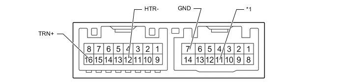
*1 TRNI
-
Remove the outer mirror control ECU assembly LH.
-
Measure the resistance according to the value(s) in the table below.
Standard Resistance (Check for Open) Tester Connection Condition Specified Condition 16 (TRN+) - 11 (TRNI) Always Below 1 Ω 12 (HTR-) - 7 (GND) Always Below 1 Ω Standard Resistance (Check for Short) Tester Connection Condition Specified Condition 16 (TRN+) - 12 (HTR-) Always 10 kΩ or higher Result Proceed to OK NG
OK
REPLACE COMBINATION METER ASSEMBLY Click here
NG
REPLACE OUTER MIRROR CONTROL ECU ASSEMBLY LH Click here
-
-
CHECK HARNESS AND CONNECTOR (REAR COMBINATION LIGHT SOCKET AND WIRE SUB-ASSEMBLY LH - COMBINATION METER ASSEMBLY AND BODY GROUND)
-
Disconnect the G195 combination meter assembly connector.
-
Disconnect the A110 headlight cord LH connector.
-
Disconnect the K12 outer mirror control ECU assembly LH connector.
-
Disconnect the R22 rear combination light socket and wire sub-assembly LH connector.
-
Measure the resistance according to the value(s) in the table below.
Standard Resistance (Check for Open) Tester Connection Condition Specified Condition R22-3 (TRN) - G195-8 (LL) Always Below 1 Ω R22-4 (E) - Body ground Always Below 1 Ω Standard Resistance (Check for Short) Tester Connection Condition Specified Condition R22-3 (TRN) - Body ground Always 10 kΩ or higher Result Proceed to OK NG
NG
REPAIR OR REPLACE HARNESS OR CONNECTOR
OK
-
-
INSPECT REAR COMBINATION LIGHT SOCKET AND WIRE SUB-ASSEMBLY LH
-
Remove the rear combination light socket and wire sub-assembly LH.
-
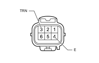
Apply battery voltage and check the operation of the rear turn signal light.
OK Battery Connection Specified Condition Positive (+) → 3 (TRN)
Negative (-) → 4 (E)
Rear turn signal light illuminates Result Proceed to OK NG
OK
REPLACE COMBINATION METER ASSEMBLY Click here
NG
REPLACE REAR COMBINATION LIGHT SOCKET AND WIRE SUB-ASSEMBLY LH Click here
-
-
CHECK TURN SIGNAL LIGHTS (RH SIDE)
-
Turn the ignition switch to ON.
-
Set the headlight dimmer switch assembly to the right turn switch position.
-
Check the operation of the turn signal lights (RH side).
Result Result Proceed to Front turn signal light (RH side) does not blink. A Side turn signal light (RH side) does not blink. B Rear turn signal light (RH side) does not blink. C
B
CHECK HARNESS AND CONNECTOR (OUTER MIRROR CONTROL ECU ASSEMBLY RH - COMBINATION METER ASSEMBLY AND BODY GROUND) Click here
C
CHECK HARNESS AND CONNECTOR (REAR COMBINATION LIGHT SOCKET AND WIRE SUB-ASSEMBLY RH - COMBINATION METER ASSEMBLY AND BODY GROUND) Click here
A
-
-
CHECK HARNESS AND CONNECTOR (HEADLIGHT CORD RH - COMBINATION METER ASSEMBLY AND BODY GROUND)
-
Disconnect the G195 combination meter assembly connector.
-
Disconnect the A112 headlight cord RH connector.
-
Disconnect the J12 outer mirror control ECU assembly RH connector.
-
Disconnect the Q31*1 or R21*2 rear combination light socket and wire sub-assembly RH connector.
-
*1: for 3 Door
-
*2: for 5 Door
-
-
Measure the resistance according to the value(s) in the table below.
Standard Resistance (Check for Open) Tester Connection Condition Specified Condition A112-4 (B) - J195-13 (LR) Always Below 1 Ω A112-3 (E) - Body ground Always Below 1 Ω Standard Resistance (Check for Short) Tester Connection Condition Specified Condition A112-4 (B) - Body ground Always 10 kΩ or higher Result Proceed to OK NG
NG
REPAIR OR REPLACE HARNESS OR CONNECTOR
OK
-
-
INSPECT HEADLIGHT CORD RH
-
Remove the headlight cord RH.
-
Measure the resistance according to the value(s) in the table below.
Standard Resistance (Check for Open) Tester Connection Condition Specified Condition 4 (B) - 1 Always Below 1 Ω 3 (E) - 2 Always Below 1 Ω Standard Resistance (Check for Short) Tester Connection Condition Specified Condition 4 (B) - 3 (E) Always 10 kΩ or higher Result Proceed to OK NG
NG
REPLACE HEADLIGHT CORD RH Click here
OK
-
-
INSPECT FRONT TURN SIGNAL LIGHT BULB SOCKET RH
-
Remove the front turn signal light bulb socket RH.
-
Apply battery voltage and check the operation of the front turn signal light.
OK Battery Connection Specified Condition Positive (+) → 1
Negative (-) → 2
Front turn signal light illuminates Result Proceed to OK NG
OK
REPLACE COMBINATION METER ASSEMBLY Click here
NG
REPLACE FRONT TURN SIGNAL LIGHT BULB SOCKET RH Click here
-
-
CHECK HARNESS AND CONNECTOR (OUTER MIRROR CONTROL ECU ASSEMBLY RH - COMBINATION METER ASSEMBLY AND BODY GROUND)
-
Disconnect the G195 combination meter assembly connector.
-
Disconnect the A112 headlight cord RH connector.
-
Disconnect the J12 outer mirror control ECU assembly RH connector.
-
Disconnect the Q31*1 or R21*2 rear combination light socket and wire sub-assembly RH connector.
-
*1: for 3 Door
-
*2: for 5 Door
-
-
Measure the resistance according to the value(s) in the table below.
Standard Resistance (Check for Open) Tester Connection Condition Specified Condition J12-11 (TRNI) - G195-13 (LR) Always Below 1 Ω J12-7 (GND) - Body ground Always Below 1 Ω Standard Resistance (Check for Short) Tester Connection Condition Specified Condition J12-11 (TRNI) - Body ground Always 10 kΩ or higher Result Proceed to OK NG
NG
REPAIR OR REPLACE HARNESS OR CONNECTOR
OK
-
-
INSPECT SIDE TURN SIGNAL LIGHT ASSEMBLY RH
-
Remove the side turn signal light assembly RH.
-
Inspect the side turn signal light assembly RH.
Result Proceed to OK NG
NG
REPLACE SIDE TURN SIGNAL LIGHT ASSEMBLY RH Click here
OK
-
-
CHECK OUTER MIRROR RETRACTOR RH
-
Disconnect the z19 outer mirror retractor RH connector.
-

*a Front view of wire harness connector
(to Outer Mirror Control ECU Assembly RH)
Apply battery voltage and check the operation of the side turn signal light.
OK Battery Connection Specified Condition Positive (+) → z19-16 (TRN+)
Negative (-) → z19-12 (HTR-)
Side turn signal light illuminates Result Proceed to OK NG
NG
REPLACE OUTER MIRROR RETRACTOR RH Click here
OK
-
-
INSPECT OUTER MIRROR CONTROL ECU ASSEMBLY RH
*1 TRNI
-
Remove the outer mirror control ECU assembly RH.
-
Measure the resistance according to the value(s) in the table below.
Standard Resistance (Check for Open) Tester Connection Condition Specified Condition 16 (TRN+) - 11 (TRNI) Always Below 1 Ω 12 (HTR-) - 7 (GND) Always Below 1 Ω Standard Resistance (Check for Short) Tester Connection Condition Specified Condition 16 (TRN+) - 12 (HTR-) Always 10 kΩ or higher Result Proceed to OK NG
OK
REPLACE COMBINATION METER ASSEMBLY Click here
NG
REPLACE OUTER MIRROR CONTROL ECU ASSEMBLY RH Click here
-
-
CHECK HARNESS AND CONNECTOR (REAR COMBINATION LIGHT SOCKET AND WIRE SUB-ASSEMBLY RH - COMBINATION METER ASSEMBLY AND BODY GROUND)
-
Disconnect the G195 combination meter assembly connector.
-
Disconnect the A112 headlight cord RH connector.
-
Disconnect the J12 outer mirror control ECU assembly RH connector.
-
Disconnect the Q31*1 or R21*2 rear combination light socket and wire sub-assembly RH connector.
-
*1: for 3 Door
-
*2: for 5 Door
-
-
Measure the resistance according to the value(s) in the table below.
Standard Resistance (Check for Open) *1: for 3 DoorTester Connection Condition Specified Condition Q31-3 (TRN) - G195-13 (LR)*1 Always Below 1 Ω R21-3 (TRN) - G195-13 (LR)*2 Always Below 1 Ω Q31-4 (E) - Body ground*1 Always Below 1 Ω R21-4 (E) - Body ground*2 Always Below 1 Ω
*2: for 5 Door
Standard Resistance (Check for Short) *1: for 3 DoorTester Connection Condition Specified Condition Q31-3 (TRN) - Body ground*1 Always 10 kΩ or higher R21-3 (TRN) - Body ground*2 Always 10 kΩ or higher
*2: for 5 Door
Result Proceed to OK NG
NG
REPAIR OR REPLACE HARNESS OR CONNECTOR
OK
-
-
INSPECT REAR COMBINATION LIGHT SOCKET AND WIRE SUB-ASSEMBLY RH
-
Remove the rear combination light socket and wire sub-assembly RH.
-
Apply battery voltage and check the operation of the rear turn signal light.
OK Battery Connection Specified Condition Positive (+) → 3 (TRN)
Negative (-) → 4 (E)
Rear turn signal light illuminates Result Proceed to OK NG
OK
REPLACE COMBINATION METER ASSEMBLY Click here
NG
REPLACE REAR COMBINATION LIGHT SOCKET AND WIRE SUB-ASSEMBLY RH Click here
-
-
INSPECT LIGHTS
-
Inspect the illumination of each turn signal light.
Result Result Proceed to LH side turn signal light does not illuminate. A RH side turn signal light does not illuminate. B
B
CHECK TURN SIGNAL LIGHTS (RH SIDE) Click here
A
-
-
CHECK TURN SIGNAL LIGHTS (LH SIDE)
-
Turn the ignition switch to ON.
-
Set the headlight dimmer switch assembly to the left turn switch position.
-
Check the operation of the turn signal lights (LH side).
Result Result Proceed to Front turn signal light (LH side) does not blink. A Side turn signal light (LH side) does not blink. B Rear turn signal light (LH side) does not blink. C
B
CHECK HARNESS AND CONNECTOR (OUTER MIRROR RETRACTOR LH - COMBINATION METER ASSEMBLY AND BODY GROUND) Click here
C
CHECK HARNESS AND CONNECTOR (REAR COMBINATION LIGHT SOCKET AND WIRE SUB-ASSEMBLY LH - COMBINATION METER ASSEMBLY AND BODY GROUND) Click here
A
-
-
CHECK HARNESS AND CONNECTOR (HEADLIGHT CORD LH - COMBINATION METER ASSEMBLY AND BODY GROUND)
-
Disconnect the G195 combination meter assembly connector.
-
Disconnect the A110 headlight cord LH connector.
-
Disconnect the K1 outer mirror retractor LH connector.
-
Disconnect the R22 rear combination light socket and wire sub-assembly LH connector.
-
Measure the resistance according to the value(s) in the table below.
Standard Resistance (Check for Open) Tester Connection Condition Specified Condition A110-4 (B) - J195-8 (LL) Always Below 1 Ω A110-3 (E) - Body ground Always Below 1 Ω Standard Resistance (Check for Short) Tester Connection Condition Specified Condition A110-4 (B) - Body ground Always 10 kΩ or higher Result Proceed to OK NG
OK
GO TO STEP 6 Click here
NG
REPAIR OR REPLACE HARNESS OR CONNECTOR
-
-
CHECK HARNESS AND CONNECTOR (OUTER MIRROR RETRACTOR LH - COMBINATION METER ASSEMBLY AND BODY GROUND)
-
Disconnect the G195 combination meter assembly connector.
-
Disconnect the A110 headlight cord LH connector.
-
Disconnect the K1 outer mirror retractor LH connector.
-
Disconnect the R22 rear combination light socket and wire sub-assembly LH connector.
-
Measure the resistance according to the value(s) in the table below.
Standard Resistance (Check for Open) Tester Connection Condition Specified Condition K1-10 (B) - G195-8 (LL) Always Below 1 Ω K1-11 (E) - Body ground Always Below 1 Ω Standard Resistance (Check for Short) Tester Connection Condition Specified Condition K1-10 (B) - Body ground Always 10 kΩ or higher Result Proceed to OK NG
NG
REPAIR OR REPLACE HARNESS OR CONNECTOR
OK
-
-
INSPECT SIDE TURN SIGNAL LIGHT ASSEMBLY LH
-
Remove the side turn signal light assembly LH.
-
Inspect the side turn signal light assembly LH.
Result Proceed to OK NG
NG
REPLACE SIDE TURN SIGNAL LIGHT ASSEMBLY LH Click here
OK
-
-
INSPECT OUTER MIRROR RETRACTOR LH
-
Remove the outer mirror retractor LH connector.
-
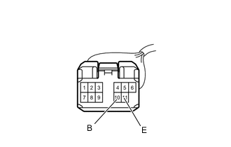
Apply battery voltage and check the operation of the side turn signal light.
OK Battery Connection Specified Condition Positive (+) → 10 (B)
Negative (-) → 11 (E)
Side turn signal light illuminates Result Proceed to OK NG
OK
REPLACE COMBINATION METER ASSEMBLY Click here
NG
REPLACE OUTER MIRROR RETRACTOR LH Click here
-
-
CHECK HARNESS AND CONNECTOR (REAR COMBINATION LIGHT SOCKET AND WIRE SUB-ASSEMBLY LH - COMBINATION METER ASSEMBLY AND BODY GROUND)
-
Disconnect the G195 combination meter assembly connector.
-
Disconnect the A110 headlight cord LH connector.
-
Disconnect the K1 outer mirror retractor LH connector.
-
Disconnect the R22 rear combination light socket and wire sub-assembly LH connector.
-
Measure the resistance according to the value(s) in the table below.
Standard Resistance (Check for Open) Tester Connection Condition Specified Condition R22-3 (TRN) - G195-8 (LL) Always Below 1 Ω R22-4 (E) - Body ground Always Below 1 Ω Standard Resistance (Check for Short) Tester Connection Condition Specified Condition R22-3 (TRN) - Body ground Always 10 kΩ or higher Result Proceed to OK NG
OK
GO TO STEP 13 Click here
NG
REPAIR OR REPLACE HARNESS OR CONNECTOR
-
-
CHECK TURN SIGNAL LIGHTS (RH SIDE)
-
Turn the ignition switch to ON.
-
Set the headlight dimmer switch assembly to the right turn switch position.
-
Check the operation of the turn signal lights (RH side).
Result Result Proceed to Front turn signal light (RH side) does not blink. A Side turn signal light (RH side) does not blink. B Rear turn signal light (RH side) does not blink. C
B
CHECK HARNESS AND CONNECTOR (OUTER MIRROR RETRACTOR RH - COMBINATION METER ASSEMBLY AND BODY GROUND) Click here
C
CHECK HARNESS AND CONNECTOR (REAR COMBINATION LIGHT SOCKET AND WIRE SUB-ASSEMBLY RH - COMBINATION METER ASSEMBLY AND BODY GROUND) Click here
A
-
-
CHECK HARNESS AND CONNECTOR (HEADLIGHT CORD RH - COMBINATION METER ASSEMBLY AND BODY GROUND)
-
Disconnect the G195 combination meter assembly connector.
-
Disconnect the A112 headlight cord RH connector.
-
Disconnect the J2 outer mirror retractor RH connector.
-
Disconnect the Q31*1 or R21*2 rear combination light socket and wire sub-assembly RH connector.
-
*1: for 3 Door
-
*2: for 5 Door
-
-
Measure the resistance according to the value(s) in the table below.
Standard Resistance (Check for Open) Tester Connection Condition Specified Condition A112-4 (B) - J195-13 (LR) Always Below 1 Ω A112-3 (E) - Body ground Always Below 1 Ω Standard Resistance (Check for Short) Tester Connection Condition Specified Condition A112-4 (B) - Body ground Always 10 kΩ or higher Result Proceed to OK NG
OK
GO TO STEP 16 Click here
NG
REPAIR OR REPLACE HARNESS OR CONNECTOR
-
-
CHECK HARNESS AND CONNECTOR (OUTER MIRROR RETRACTOR RH - COMBINATION METER ASSEMBLY AND BODY GROUND)
-
Disconnect the G195 combination meter assembly connector.
-
Disconnect the A112 headlight cord RH connector.
-
Disconnect the J2 outer mirror retractor RH connector.
-
Disconnect the Q31*1 or R21*2 rear combination light socket and wire sub-assembly RH connector.
-
*1: for 3 Door
-
*2: for 5 Door
-
-
Measure the resistance according to the value(s) in the table below.
Standard Resistance (Check for Open) Tester Connection Condition Specified Condition J2-10 (B) - G195-13 (LR) Always Below 1 Ω J2-11 (E) - Body ground Always Below 1 Ω Standard Resistance (Check for Short) Tester Connection Condition Specified Condition J2-10 (B) - Body ground Always 10 kΩ or higher Result Proceed to OK NG
NG
REPAIR OR REPLACE HARNESS OR CONNECTOR
OK
-
-
INSPECT SIDE TURN SIGNAL LIGHT ASSEMBLY RH
-
Remove the side turn signal light assembly RH.
-
Inspect the side turn signal light assembly RH.
Result Proceed to OK NG
NG
REPLACE SIDE TURN SIGNAL LIGHT ASSEMBLY RH Click here
OK
-
-
INSPECT OUTER MIRROR RETRACTOR RH
-
Remove the outer mirror retractor RH connector.
-
Apply battery voltage and check the operation of the side turn signal light.
OK Battery Connection Specified Condition Positive (+) → 10 (B)
Negative (-) → 11 (E)
Side turn signal light illuminates Result Proceed to OK NG
OK
REPLACE COMBINATION METER ASSEMBLY Click here
NG
REPLACE OUTER MIRROR RETRACTOR RH Click here
-
-
CHECK HARNESS AND CONNECTOR (REAR COMBINATION LIGHT SOCKET AND WIRE SUB-ASSEMBLY RH - COMBINATION METER ASSEMBLY AND BODY GROUND)
-
Disconnect the G195 combination meter assembly connector.
-
Disconnect the A112 headlight cord RH connector.
-
Disconnect the J2 outer mirror retractor RH connector.
-
Disconnect the Q31*1 or R21*2 rear combination light socket and wire sub-assembly RH connector.
-
*1: for 3 Door
-
*2: for 5 Door
-
-
Measure the resistance according to the value(s) in the table below.
Standard Resistance (Check for Open) *1: for 3 DoorTester Connection Condition Specified Condition Q31-3 (TRN) - G195-13 (LR)*1 Always Below 1 Ω R21-3 (TRN) - G195-13 (LR)*2 Always Below 1 Ω Q31-4 (E) - Body ground*1 Always Below 1 Ω R21-4 (E) - Body ground*2 Always Below 1 Ω
*2: for 5 Door
Standard Resistance (Check for Short) *1: for 3 DoorTester Connection Condition Specified Condition Q31-3 (TRN) - Body ground*1 Always 10 kΩ or higher R21-3 (TRN) - Body ground*2 Always 10 kΩ or higher
*2: for 5 Door
Result Proceed to OK NG
OK
GO TO STEP 23 Click here
NG
REPAIR OR REPLACE HARNESS OR CONNECTOR
-
-
INSPECT LIGHTS
-
Inspect the illumination of each turn signal light.
Result Result Proceed to LH side turn signal light does not illuminate. A RH side turn signal light does not illuminate. B
B
CHECK TURN SIGNAL LIGHTS (RH SIDE) Click here
A
-
-
CHECK TURN SIGNAL LIGHTS (LH SIDE)
-
Turn the ignition switch to ON.
-
Set the headlight dimmer switch assembly to the left turn switch position.
-
Check the operation of the turn signal lights (LH side).
Result Result Proceed to Front turn signal light (LH side) does not blink. A Side turn signal light (LH side) does not blink. B Rear turn signal light (LH side) does not blink. C
B
CHECK HARNESS AND CONNECTOR (OUTER MIRROR CONTROL ECU ASSEMBLY LH - COMBINATION METER ASSEMBLY AND BODY GROUND) Click here
C
CHECK HARNESS AND CONNECTOR (REAR COMBINATION LIGHT SOCKET AND WIRE SUB-ASSEMBLY LH - COMBINATION METER ASSEMBLY AND BODY GROUND) Click here
A
-
-
CHECK HARNESS AND CONNECTOR (NO. 1 HEADLIGHT ECU SUB-ASSEMBLY LH - COMBINATION METER ASSEMBLY AND BODY GROUND)
-
Disconnect the G195 combination meter assembly connector.
-
Disconnect the A102 No. 1 headlight ECU sub-assembly LH connector.
-
Disconnect the K12 outer mirror control ECU assembly LH connector.
-
Disconnect the R22 rear combination light socket and wire sub-assembly LH connector.
-
Measure the resistance according to the value(s) in the table below.
Standard Resistance (Check for Open) Tester Connection Condition Specified Condition A102-11 (TNS) - J195-8 (LL) Always Below 1 Ω A102-12 (GND) - Body ground Always Below 1 Ω Standard Resistance (Check for Short) Tester Connection Condition Specified Condition A102-11 (TNS) - Body ground Always 10 kΩ or higher Result Proceed to OK NG
NG
REPAIR OR REPLACE HARNESS OR CONNECTOR
OK
-
-
INSPECT FRONT TURN SIGNAL LIGHT BULB SOCKET LH
-
Remove the front turn signal light bulb socket LH.
-
Apply battery voltage and check the operation of the front turn signal light.
OK Battery Connection Specified Condition Positive (+) → 1
Negative (-) → 2
Front turn signal light illuminates Result Proceed to OK NG
NG
REPLACE FRONT TURN SIGNAL LIGHT BULB SOCKET LH Click here
OK
-
-
INSPECT HEADLIGHT UNIT ASSEMBLY LH
-
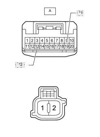
*1 TURN+ *2 TURN- Remove the headlight unit assembly LH.
-
Measure the resistance according to the value(s) in the table below.
Standard Resistance (Check for Open) Tester Connection Condition Specified Condition A-9 (TURN+) - 1 Always Below 1 Ω A-13 (TURN-) - 2 Always Below 1 Ω Standard Resistance (Check for Short) Tester Connection Condition Specified Condition A-9 (TURN+) - A-13 (TURN-) Always 10 kΩ or higher Result Proceed to OK NG
NG
REPLACE HEADLIGHT UNIT ASSEMBLY LH Click here
OK
-
-
INSPECT NO. 1 HEADLIGHT ECU SUB-ASSEMBLY LH
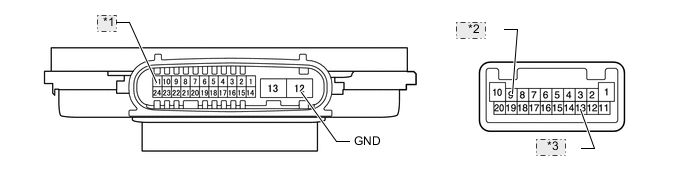
*1 TNS *2 TURN+ *3 TURN-
-
Remove the No. 1 headlight ECU sub-assembly LH.
-
Measure the resistance according to the value(s) in the table below.
Standard Resistance (Check for Open) Tester Connection Condition Specified Condition 11 (TNS) - 9 (TURN+) Always Below 1 Ω 12 (GND) - 13 (TURN-) Always Below 1 Ω Standard Resistance (Check for Short) Tester Connection Condition Specified Condition 11 (TNS) - 12 (GND) Always 10 kΩ or higher Result Proceed to OK NG
OK
REPLACE COMBINATION METER ASSEMBLY Click here
NG
REPLACE NO. 1 HEADLIGHT ECU SUB-ASSEMBLY LH Click here
-
-
CHECK HARNESS AND CONNECTOR (OUTER MIRROR CONTROL ECU ASSEMBLY LH - COMBINATION METER ASSEMBLY AND BODY GROUND)
-
Disconnect the G195 combination meter assembly connector.
-
Disconnect the A102 No. 1 headlight ECU sub-assembly LH connector.
-
Disconnect the K12 outer mirror control ECU assembly LH connector.
-
Disconnect the R22 rear combination light socket and wire sub-assembly LH connector.
-
Measure the resistance according to the value(s) in the table below.
Standard Resistance (Check for Open) Tester Connection Condition Specified Condition K12-11 (TRNI) - G195-8 (LL) Always Below 1 Ω K12-7 (GND) - Body ground Always Below 1 Ω Standard Resistance (Check for Short) Tester Connection Condition Specified Condition K12-11 (TRNI) - Body ground Always 10 kΩ or higher Result Proceed to OK NG
OK
GO TO STEP 9 Click here
NG
REPAIR OR REPLACE HARNESS OR CONNECTOR
-
-
CHECK HARNESS AND CONNECTOR (REAR COMBINATION LIGHT SOCKET AND WIRE SUB-ASSEMBLY LH - COMBINATION METER ASSEMBLY AND BODY GROUND)
-
Disconnect the G195 combination meter assembly connector.
-
Disconnect the A102 No. 1 headlight ECU sub-assembly LH connector.
-
Disconnect the K12 outer mirror control ECU assembly LH connector.
-
Disconnect the R22 rear combination light socket and wire sub-assembly LH connector.
-
Measure the resistance according to the value(s) in the table below.
Standard Resistance (Check for Open) Tester Connection Condition Specified Condition R22-3 (TRN) - G195-8 (LL) Always Below 1 Ω R22-4 (E) - Body ground Always Below 1 Ω Standard Resistance (Check for Short) Tester Connection Condition Specified Condition R22-3 (TRN) - Body ground Always 10 kΩ or higher Result Proceed to OK NG
OK
GO TO STEP 13 Click here
NG
REPAIR OR REPLACE HARNESS OR CONNECTOR
-
-
CHECK TURN SIGNAL LIGHTS (RH SIDE)
-
Turn the ignition switch to ON.
-
Set the headlight dimmer switch assembly to the right turn switch position.
-
Check the operation of the turn signal lights (RH side).
Result Result Proceed to Front turn signal light (RH side) does not blink. A Side turn signal light (RH side) does not blink. B Rear turn signal light (RH side) does not blink. C
B
CHECK HARNESS AND CONNECTOR (OUTER MIRROR CONTROL ECU ASSEMBLY RH - COMBINATION METER ASSEMBLY AND BODY GROUND) Click here
C
CHECK HARNESS AND CONNECTOR (REAR COMBINATION LIGHT SOCKET AND WIRE SUB-ASSEMBLY RH - COMBINATION METER ASSEMBLY AND BODY GROUND) Click here
A
-
-
CHECK HARNESS AND CONNECTOR (NO. 1 HEADLIGHT ECU SUB-ASSEMBLY RH - COMBINATION METER ASSEMBLY AND BODY GROUND)
-
Disconnect the G195 combination meter assembly connector.
-
Disconnect the A103 No. 1 headlight ECU sub-assembly RH connector.
-
Disconnect the J12 outer mirror control ECU assembly RH connector.
-
Disconnect the Q31*1 or R21*2 rear combination light socket and wire sub-assembly RH connector.
-
*1: for 3 Door
-
*2: for 5 Door
-
-
Measure the resistance according to the value(s) in the table below.
Standard Resistance (Check for Open) Tester Connection Condition Specified Condition A103-11 (TNS) - J195-13 (LR) Always Below 1 Ω A103-12 (GND) - Body ground Always Below 1 Ω Standard Resistance (Check for Short) Tester Connection Condition Specified Condition A103-11 (TNS) - Body ground Always 10 kΩ or higher Result Proceed to OK NG
NG
REPAIR OR REPLACE HARNESS OR CONNECTOR
OK
-
-
INSPECT FRONT TURN SIGNAL LIGHT BULB SOCKET RH
-
Remove the front turn signal light bulb socket RH.
-
Apply battery voltage and check the operation of the front turn signal light.
OK Battery Connection Specified Condition Positive (+) → 1
Negative (-) → 2
Front turn signal light illuminates Result Proceed to OK NG
NG
REPLACE FRONT TURN SIGNAL LIGHT BULB SOCKET RH Click here
OK
-
-
INSPECT HEADLIGHT UNIT ASSEMBLY RH
-
*1 TURN+ *2 TURN- Remove the headlight unit assembly RH.
-
Measure the resistance according to the value(s) in the table below.
Standard Resistance (Check for Open) Tester Connection Condition Specified Condition A-9 (TURN+) - 1 Always Below 1 Ω A-13 (TURN-) - 2 Always Below 1 Ω Standard Resistance (Check for Short) Tester Connection Condition Specified Condition A-9 (TURN+) - A-13 (TURN-) Always 10 kΩ or higher Result Proceed to OK NG
NG
REPLACE HEADLIGHT UNIT ASSEMBLY RH Click here
OK
-
-
INSPECT NO. 1 HEADLIGHT ECU SUB-ASSEMBLY RH
*1 TNS *2 TURN+ *3 TURN-
-
Remove the No. 1 headlight ECU sub-assembly RH.
-
Measure the resistance according to the value(s) in the table below.
Standard Resistance (Check for Open) Tester Connection Condition Specified Condition 11 (TNS) - 9 (TURN+) Always Below 1 Ω 12 (GND) - 13 (TURN-) Always Below 1 Ω Standard Resistance (Check for Short) Tester Connection Condition Specified Condition 11 (TNS) - 12 (GND) Always 10 kΩ or higher Result Proceed to OK NG
OK
REPLACE COMBINATION METER ASSEMBLY Click here
NG
REPLACE NO. 1 HEADLIGHT ECU SUB-ASSEMBLY RH Click here
-
-
CHECK HARNESS AND CONNECTOR (OUTER MIRROR CONTROL ECU ASSEMBLY RH - COMBINATION METER ASSEMBLY AND BODY GROUND)
-
Disconnect the G195 combination meter assembly connector.
-
Disconnect the A103 No. 1 headlight ECU sub-assembly RH connector.
-
Disconnect the J12 outer mirror control ECU assembly RH connector.
-
Disconnect the Q31*1 or R21*2 rear combination light socket and wire sub-assembly RH connector.
-
*1: for 3 Door
-
*2: for 5 Door
-
-
Measure the resistance according to the value(s) in the table below.
Standard Resistance (Check for Open) Tester Connection Condition Specified Condition J12-11 (TRNI) - G195-13 (LR) Always Below 1 Ω J12-7 (GND) - Body ground Always Below 1 Ω Standard Resistance (Check for Short) Tester Connection Condition Specified Condition J12-11 (TRNI) - Body ground Always 10 kΩ or higher Result Proceed to OK NG
OK
GO TO STEP 19 Click here
NG
REPAIR OR REPLACE HARNESS OR CONNECTOR
-
-
CHECK HARNESS AND CONNECTOR (REAR COMBINATION LIGHT SOCKET AND WIRE SUB-ASSEMBLY RH - COMBINATION METER ASSEMBLY AND BODY GROUND)
-
Disconnect the G195 combination meter assembly connector.
-
Disconnect the A103 No. 1 headlight ECU sub-assembly RH connector.
-
Disconnect the J12 outer mirror control ECU assembly RH connector.
-
Disconnect the Q31*1 or R21*2 rear combination light socket and wire sub-assembly RH connector.
-
*1: for 3 Door
-
*2: for 5 Door
-
-
Measure the resistance according to the value(s) in the table below.
Standard Resistance (Check for Open) *1: for 3 DoorTester Connection Condition Specified Condition Q31-3 (TRN) - G195-13 (LR)*1 Always Below 1 Ω R21-3 (TRN) - G195-13 (LR)*2 Always Below 1 Ω Q31-4 (E) - Body ground*1 Always Below 1 Ω R21-4 (E) - Body ground*2 Always Below 1 Ω
*2: for 5 Door
Standard Resistance (Check for Short) *1: for 3 DoorTester Connection Condition Specified Condition Q31-3 (TRN) - Body ground*1 Always 10 kΩ or higher R21-3 (TRN) - Body ground*2 Always 10 kΩ or higher
*2: for 5 Door
Result Proceed to OK NG
OK
GO TO STEP 23 Click here
NG
REPAIR OR REPLACE HARNESS OR CONNECTOR
-
-
INSPECT LIGHTS
-
Inspect the illumination of each turn signal light.
Result Result Proceed to LH side turn signal light does not illuminate. A RH side turn signal light does not illuminate. B
B
CHECK TURN SIGNAL LIGHTS (RH SIDE) Click here
A
-
-
CHECK TURN SIGNAL LIGHTS (LH SIDE)
-
Turn the ignition switch to ON.
-
Set the headlight dimmer switch assembly to the left turn switch position.
-
Check the operation of the turn signal lights (LH side).
Result Result Proceed to Front turn signal light (LH side) does not blink. A Side turn signal light (LH side) does not blink. B Rear turn signal light (LH side) does not blink. C
B
CHECK HARNESS AND CONNECTOR (OUTER MIRROR RETRACTOR LH - COMBINATION METER ASSEMBLY AND BODY GROUND) Click here
C
CHECK HARNESS AND CONNECTOR (REAR COMBINATION LIGHT SOCKET AND WIRE SUB-ASSEMBLY LH - COMBINATION METER ASSEMBLY AND BODY GROUND) Click here
A
-
-
CHECK HARNESS AND CONNECTOR (NO. 1 HEADLIGHT ECU SUB-ASSEMBLY LH - COMBINATION METER ASSEMBLY AND BODY GROUND)
-
Disconnect the G195 combination meter assembly connector.
-
Disconnect the A102 No. 1 headlight ECU sub-assembly LH connector.
-
Disconnect the K1 outer mirror retractor LH connector.
-
Disconnect the R22 rear combination light socket and wire sub-assembly LH connector.
-
Measure the resistance according to the value(s) in the table below.
Standard Resistance (Check for Open) Tester Connection Condition Specified Condition A102-11 (TNS) - J195-8 (LL) Always Below 1 Ω A102-12 (GND) - Body ground Always Below 1 Ω Standard Resistance (Check for Short) Tester Connection Condition Specified Condition A102-11 (TNS) - Body ground Always 10 kΩ or higher Result Proceed to OK NG
OK
GO TO STEP 40 Click here
NG
REPAIR OR REPLACE HARNESS OR CONNECTOR
-
-
CHECK HARNESS AND CONNECTOR (OUTER MIRROR RETRACTOR LH - COMBINATION METER ASSEMBLY AND BODY GROUND)
-
Disconnect the G195 combination meter assembly connector.
-
Disconnect the A102 No. 1 headlight ECU sub-assembly LH connector.
-
Disconnect the K1 outer mirror retractor LH connector.
-
Disconnect the R22 rear combination light socket and wire sub-assembly LH connector.
-
Measure the resistance according to the value(s) in the table below.
Standard Resistance (Check for Open) Tester Connection Condition Specified Condition K1-10 (B) - G195-8 (LL) Always Below 1 Ω K1-11 (E) - Body ground Always Below 1 Ω Standard Resistance (Check for Short) Tester Connection Condition Specified Condition K1-10 (B) - Body ground Always 10 kΩ or higher Result Proceed to OK NG
OK
GO TO STEP 28 Click here
NG
REPAIR OR REPLACE HARNESS OR CONNECTOR
-
-
CHECK HARNESS AND CONNECTOR (REAR COMBINATION LIGHT SOCKET AND WIRE SUB-ASSEMBLY LH - COMBINATION METER ASSEMBLY AND BODY GROUND)
-
Disconnect the G195 combination meter assembly connector.
-
Disconnect the A102 No. 1 headlight ECU sub-assembly LH connector.
-
Disconnect the K1 outer mirror retractor LH connector.
-
Disconnect the R22 rear combination light socket and wire sub-assembly LH connector.
-
Measure the resistance according to the value(s) in the table below.
Standard Resistance (Check for Open) Tester Connection Condition Specified Condition R22-3 (TRN) - G195-8 (LL) Always Below 1 Ω R22-4 (E) - Body ground Always Below 1 Ω Standard Resistance (Check for Short) Tester Connection Condition Specified Condition R22-3 (TRN) - Body ground Always 10 kΩ or higher Result Proceed to OK NG
OK
GO TO STEP 13 Click here
NG
REPAIR OR REPLACE HARNESS OR CONNECTOR
-
-
CHECK TURN SIGNAL LIGHTS (RH SIDE)
-
Turn the ignition switch to ON.
-
Set the headlight dimmer switch assembly to the right turn switch position.
-
Check the operation of the turn signal lights (RH side).
Result Result Proceed to Front turn signal light (RH side) does not blink. A Side turn signal light (RH side) does not blink. B Rear turn signal light (RH side) does not blink. C
B
CHECK HARNESS AND CONNECTOR (OUTER MIRROR RETRACTOR RH - COMBINATION METER ASSEMBLY AND BODY GROUND) Click here
C
CHECK HARNESS AND CONNECTOR (REAR COMBINATION LIGHT SOCKET AND WIRE SUB-ASSEMBLY RH - COMBINATION METER ASSEMBLY AND BODY GROUND) Click here
A
-
-
CHECK HARNESS AND CONNECTOR (NO. 1 HEADLIGHT ECU SUB-ASSEMBLY RH - COMBINATION METER ASSEMBLY AND BODY GROUND)
-
Disconnect the G195 combination meter assembly connector.
-
Disconnect the A103 No. 1 headlight ECU sub-assembly RH connector.
-
Disconnect the J2 outer mirror retractor RH connector.
-
Disconnect the Q31*1 or R21*2 rear combination light socket and wire sub-assembly RH connector.
-
*1: for 3 Door
-
*2: for 5 Door
-
-
Measure the resistance according to the value(s) in the table below.
Standard Resistance (Check for Open) Tester Connection Condition Specified Condition A103-11 (TNS) - J195-13 (LR) Always Below 1 Ω A103-12 (GND) - Body ground Always Below 1 Ω Standard Resistance (Check for Short) Tester Connection Condition Specified Condition A103-11 (TNS) - Body ground Always 10 kΩ or higher Result Proceed to OK NG
OK
GO TO STEP 47 Click here
NG
REPAIR OR REPLACE HARNESS OR CONNECTOR
-
-
CHECK HARNESS AND CONNECTOR (OUTER MIRROR RETRACTOR RH - COMBINATION METER ASSEMBLY AND BODY GROUND)
-
Disconnect the G195 combination meter assembly connector.
-
Disconnect the A103 No. 1 headlight ECU sub-assembly RH connector.
-
Disconnect the J2 outer mirror retractor RH connector.
-
Disconnect the Q31*1 or R21*2 rear combination light socket and wire sub-assembly RH connector.
-
*1: for 3 Door
-
*2: for 5 Door
-
-
Measure the resistance according to the value(s) in the table below.
Standard Resistance (Check for Open) Tester Connection Condition Specified Condition J2-10 (B) - G195-13 (LR) Always Below 1 Ω J2-11 (E) - Body ground Always Below 1 Ω Standard Resistance (Check for Short) Tester Connection Condition Specified Condition J2-10 (B) - Body ground Always 10 kΩ or higher Result Proceed to OK NG
OK
GO TO STEP 34 Click here
NG
REPAIR OR REPLACE HARNESS OR CONNECTOR
-
-
CHECK HARNESS AND CONNECTOR (REAR COMBINATION LIGHT SOCKET AND WIRE SUB-ASSEMBLY RH - COMBINATION METER ASSEMBLY AND BODY GROUND)
-
Disconnect the G195 combination meter assembly connector.
-
Disconnect the A103 No. 1 headlight ECU sub-assembly RH connector.
-
Disconnect the J2 outer mirror retractor RH connector.
-
Disconnect the Q31*1 or R21*2 rear combination light socket and wire sub-assembly RH connector.
-
*1: for 3 Door
-
*2: for 5 Door
-
-
Measure the resistance according to the value(s) in the table below.
Standard Resistance (Check for Open) *1: for 3 DoorTester Connection Condition Specified Condition Q31-3 (TRN) - G195-13 (LR)*1 Always Below 1 Ω R21-3 (TRN) - G195-13 (LR)*2 Always Below 1 Ω Q31-4 (E) - Body ground*1 Always Below 1 Ω R21-4 (E) - Body ground*2 Always Below 1 Ω
*2: for 5 Door
Standard Resistance (Check for Short) *1: for 3 DoorTester Connection Condition Specified Condition Q31-3 (TRN) - Body ground*1 Always 10 kΩ or higher R21-3 (TRN) - Body ground*2 Always 10 kΩ or higher
*2: for 5 Door
Result Proceed to OK NG
OK
GO TO STEP 23 Click here
NG
REPAIR OR REPLACE HARNESS OR CONNECTOR
-