METER / GAUGE SYSTEM, Diagnostic DTC:B2660
| DTC Code | DTC Name |
|---|---|
| B2660 | Steering Wheel Switch Malfunction |
DESCRIPTION
This code is output when any steering pad switch is continuously on for a period of 60 seconds.
| DTC Code | DTC Detection Condition | Trouble Area |
|---|---|---|
| B2660 | The driving support switch control ECU detects a malfunction in the steering pad switch. |
|
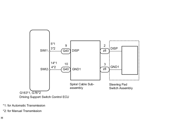
WIRING DIAGRAM
PROCEDURE
-
READ VALUE USING GTS
-
Using the GTS, read the Data List Click here.
D-SEAT SW Tester Display Measurement Item/Range Normal Condition Diagnostic Note Steering Wheel Menu Switch MENU switch/OFF or ON OFF: MENU switch off - ON: MENU switch on Steering Wheel Enter Switch ENTER switch/OFF or ON OFF: ENTER switch off - ON: ENTER switch on Steering Wheel Up Switch UP/DOWN UP switch/OFF or ON OFF: UP/DOWN UP switch off - ON: UP/DOWN UP switch on Steering Wheel Down Switch UP/DOWN DOWN switch/OFF or ON OFF: UP/DOWN DOWN switch off - ON: UP/DOWN DOWN switch on OK The value displayed on the intelligent tester changes with the actual steering pad switch operation.
OK 
REPLACE DRIVING SUPPORT SWITCH CONTROL ECU Click here
NG 
-
-
INSPECT STEERING PAD SWITCH ASSEMBLY
-
Remove the steering pad switch assembly Click here.
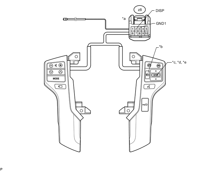
Text in Illustration *a Front view of wire harness connector
(to spiral cable sub-assembly)
*b MENU switch *c ENTER switch *d UP/DOWN UP switch *e UP/DOWN DOWN switch - - -
Measure the resistance according to the value(s) in the table below.
Standard Resistance Tester Connection Condition Specified Condition z8-2 (DISP) - z8-3 (GND1) MENU switch pushed Below 2.5 Ω ENTER switch pushed 313 to 346 Ω UP/DOWN UP switch pushed 3049 to 3370 Ω UP/DOWN DOWN switch pushed 959 to 1060 Ω switch off 95 to 105 kΩ
NG
REPLACE STEERING PAD SWITCH ASSEMBLY Click here
OK
-
-
CHECK HARNESS AND CONNECTOR (SPIRAL CABLE SUB-ASSEMBLY - DRIVING SUPPORT SWITCH CONTROL ECU)
-
Disconnect the G163*1 or G76*2 driving support switch control ECU connector.
-
*1: for Automatic Transmission
-
*2: for Manual Transmission
-
-
Disconnect the G40 spiral cable sub-assembly connector.
-
Measure the resistance according to the value(s) in the table below.
Standard Resistance for Automatic Transmission Tester Connection Condition Specified Condition G40-9 (DISP) - G163-5 (SWI1) Always Below 1 Ω G40-10 (GND1) - G163-14 (SWI2) Always Below 1 Ω G40-9 (DISP) - G40-2 (ECC) Always 10 kΩ or higher G40-9 (DISP) - G40-4 (EAU) Always 10 kΩ or higher G40-9 (DISP) -G40-10 (GND1) Always 10 kΩ or higher G40-9 (DISP) - Body ground Always 10 kΩ or higher G40-10 (GND1) - Body ground Always 10 kΩ or higher for Manual Transmission Tester Connection Condition Specified Condition G40-9 (DISP) - G76-3 (SWI1) Always Below 1 Ω G40-10 (GND1) - G76-4 (SWI2) Always Below 1 Ω G40-9 (DISP) - G40-2 (ECC) Always 10 kΩ or higher G40-9 (DISP) - G40-4 (EAU) Always 10 kΩ or higher G40-9 (DISP) -G40-10 (GND1) Always 10 kΩ or higher G40-9 (DISP) - Body ground Always 10 kΩ or higher G40-10 (GND1) - Body ground Always 10 kΩ or higher
NG
REPAIR OR REPLACE HARNESS AND CONNECTOR
OK
-
-
INSPECT SPIRAL CABLE SUB-ASSEMBLY
-
Set the spiral cable to the center position Click here.
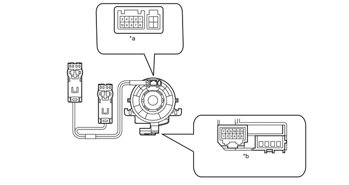
Text in Illustration *a Connector A *b Connector B -
Measure the resistance according to the value(s) in the table below.
Standard Resistance Tester Connection Condition Specified Condition A-2 - B-9 Always Below 1 Ω A-3 - B-10 Always Below 1 Ω A-2 - A-3 Always 10 kΩ or higher A-2 - A-6 Always 10 kΩ or higher A-2 - A-8 Always 10 kΩ or higher A-2 - Body ground Always 10 kΩ or higher A-3 - Body ground Always 10 kΩ or higher
OK
REPLACE DRIVING SUPPORT SWITCH CONTROL ECU Click here
NG
REPLACE SPIRAL CABLE SUB-ASSEMBLY Click here
-