METER / GAUGE SYSTEM, Diagnostic DTC:B1500
| DTC Code | DTC Name |
|---|---|
| B1500 | Fuel Sender Open Detected |
DESCRIPTION
This DTC is stored when the combination meter assembly detects a fuel sender gauge assembly malfunction via a direct line.
| DTC Code | DTC Detection Condition | Trouble Area |
|---|---|---|
| B1500 | Both conditions are met:
|
|
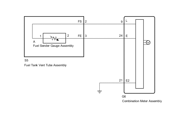
WIRING DIAGRAM
Figure 1. except 5L-E (for 5Door)
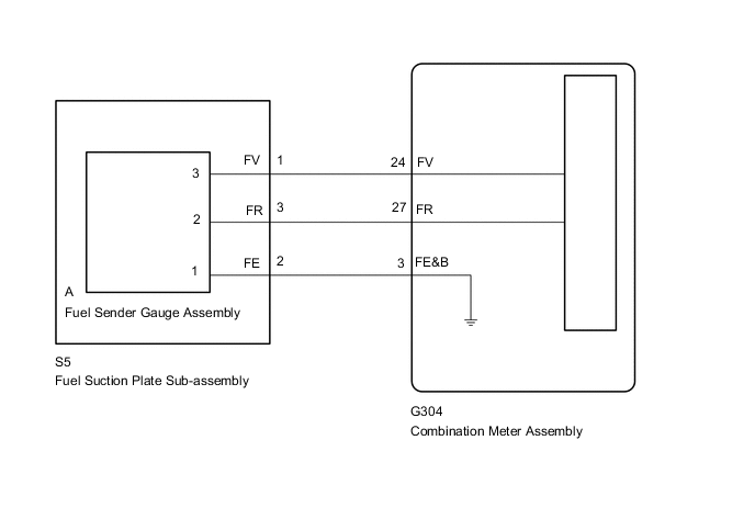
Figure 2. except 5L-E (for 3Door)
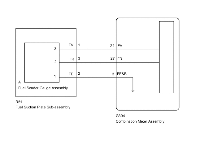
Figure 3. for 5L-E
CAUTION / NOTICE / HINT
Note
When replacing the combination meter assembly, always replace it with a new one. If a combination meter assembly which was installed to another vehicle is used, the information stored in it will not match the information from the vehicle and a DTC may be stored.
PROCEDURE
-
READ VALUE USING GTS (FUEL INPUT)
-
Connect the GTS to the DLC3.
-
Turn the engine switch on (IG).
-
Turn the GTS on.
-
Enter the following menus: Body Electrical / Combination Meter / Data List.
-
Read the Data List according to the display on the GTS.
Combination Meter Tester Display Measurement Item/Range Normal Condition Diagnostic Note Fuel Input Fuel input/Min.: 0, Max.: 127.5 Current fuel level displayed Unit: L Result Result Proceed to Fuel level data can be displayed on the GTS A Fuel level data cannot be displayed on the GTS B
A 
REPLACE COMBINATION METER ASSEMBLY Click here
B 
-
-
CHECK VEHICLE TYPE
-
Check the vehicle type.
Result Result Proceed to except 5L-E A for 5L-E B
B 
CHECK HARNESS AND CONNECTOR (FUEL GAUGE CIRCUIT) Click here
A
-
-
CHECK FUEL SENDER GAUGE ASSEMBLY (POWER SOURCE)
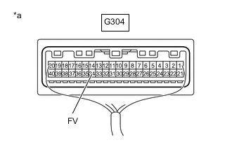
*a Component with harness connected
(Combination Meter Assembly)
-
Measure the voltage according to the value(s) in the table below.
Standard Voltage Tester Connection Switch Condition Specified Condition G304-24 (FV) - Body ground Engine switch on (IG) 4.5 to 5.5 V Result Proceed to OK NG
NG
REPLACE COMBINATION METER ASSEMBLY Click here
OK
-
-
CHECK FUEL SENDER GAUGE ASSEMBLY
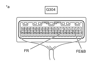
*a Component with harness connected
(Combination Meter Assembly)
-
Measure the voltage according to the value(s) in the table below.
Standard Voltage Tester Connection Switch Condition Specified Condition G304-27 (FR) - G304-3 (FE&B) Engine switch on (IG) 0.2 to 4.7 V Result Proceed to OK NG
OK
REPLACE COMBINATION METER ASSEMBLY Click here
NG
-
-
CHECK HARNESS AND CONNECTOR (FUEL SUCTION PLATE SUB-ASSEMBLY - COMBINATION METER ASSEMBLY)
-
Disconnect the S5*1 or R51*2 fuel suction plate sub-assembly connector.
-
*1: for 5Door
-
*2: for 3Door
-
-
Disconnect the G304 combination meter assembly connector.
-
Measure the resistance according to the value(s) in the table below.
Standard Resistance (for 5Door) Tester Connection Condition Specified Condition S5-3 (FR) - G304-27 (FR) Always Below 1 Ω S5-2 (FE) - G304-3 (FE&B) Always Below 1 Ω S5-1 (FV) - G304-24 (FV) Always Below 1 Ω G304-27 (FR) - Body ground Always 10 kΩ or higher G304-3 (FE&B) - Body ground Always 10 kΩ or higher G304-24 (FV) - Body ground Always 10 kΩ or higher Standard Resistance (for 3Door) Tester Connection Condition Specified Condition R51-3 (FR) - G304-27 (FR) Always Below 1 Ω R51-2 (FE) - G304-3 (FE&B) Always Below 1 Ω R51-1 (FV) - G304-24 (FV) Always Below 1 Ω G304-27 (FR) - Body ground Always 10 kΩ or higher G304-3 (FE&B) - Body ground Always 10 kΩ or higher G304-24 (FV) - Body ground Always 10 kΩ or higher Result Proceed to OK NG
NG
REPAIR OR REPLACE HARNESS OR CONNECTOR
OK
-
-
INSPECT FUEL SENDER GAUGE ASSEMBLY
-
Remove the fuel sender gauge assembly.
-
for Single Tank Type (for 1GR-FE)
-
for Single Tank Type (for 1KD-FTV)
-
for Single Tank Type (for 1GD-FTV)
-
for Single Tank Type (for 2TR-FE)
-
for Double Tank Type (for 1GR-FE)
-
for Double Tank Type (for 1KD-FTV)
-
for Double Tank Type (for 1GD-FTV)
-
for Double Tank Type (for 2TR-FE)
-
-
Inspect the fuel sender gauge assembly.
-
for Single Tank Type (for 1GR-FE)
-
for Single Tank Type (for 1KD-FTV)
-
for Single Tank Type (for 1GD-FTV)
-
for Single Tank Type (for 2TR-FE)
-
for Double Tank Type (for 1GR-FE)
-
for Double Tank Type (for 1KD-FTV)
-
for Double Tank Type (for 1GD-FTV)
-
for Double Tank Type (for 2TR-FE)
Result Proceed to OK NG -
NG
REPLACE FUEL SENDER GAUGE ASSEMBLY for Single Tank Type (for 1GR-FE) Click here for Single Tank Type (for 1KD-FTV) Click here for Single Tank Type (for 1GD-FTV) Click here for Single Tank Type (for 2TR-FE) Click here for Double Tank Type (for 1GR-FE) Click here for Double Tank Type (for 1KD-FTV) Click here for Double Tank Type (for 1GD-FTV) Click here for Double Tank Type (for 2TR-FE) Click here
OK
-
-
INSPECT FUEL SUCTION PLATE SUB-ASSEMBLY
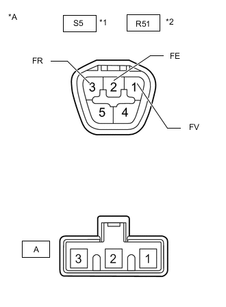
*A Component without harness connected
(Fuel Suction Plate Sub-assembly)
*1 for 5Door *2 for 3Door
-
Measure the resistance according to the value(s) in the table below.
Standard Resistance (for 5Door) Tester Connection Condition Specified Condition S5-1 (FV) - A-3 Always Below 1 Ω S5-2 (FE) - A-2 Always Below 1 Ω S5-3 (FR) - A-1 Always Below 1 Ω Standard Resistance (for 3Door) Tester Connection Condition Specified Condition R51-1 (FV) - A-3 Always Below 1 Ω R51-2 (FE) - A-2 Always Below 1 Ω R51-3 (FR) - A-1 Always Below 1 Ω Result Proceed to OK NG
OK
REPLACE COMBINATION METER ASSEMBLY Click here
NG
REPLACE FUEL SUCTION PLATE SUB-ASSEMBLY for Single Tank Type (for 1GR-FE) Click here for Single Tank Type (for 1KD-FTV) Click here for Single Tank Type (for 1GD-FTV) Click here for Single Tank Type (for 2TR-FE) Click here for Double Tank Type (for 1GR-FE) Click here for Double Tank Type (for 1KD-FTV) Click here for Double Tank Type (for 1GD-FTV) Click here for Double Tank Type (for 2TR-FE) Click here
-
-
CHECK HARNESS AND CONNECTOR (FUEL GAUGE CIRCUIT)
-
Disconnect the G6 combination meter assembly connector.
-
Disconnect the S5 fuel sender gauge assembly connector.
-
Measure the resistance according to the value(s) in the table below.
Standard Resistance Tester Connection Condition Specified Condition G6-9 (L) - S5-2 (FS) Always Below 1 Ω G6-24 (E) - S5-3 (FE) Always Below 1 Ω G6-21 (E2) - Body ground Always Below 1 Ω G6-16 (L) or S5-2 (FS) - Body ground Always 10 kΩ or higher G6-15 (E) or S5-3 (FE) - Body ground Always 10 kΩ or higher Result Proceed to OK NG
NG
REPAIR OR REPLACE HARNESS OR CONNECTOR
OK
-
-
INSPECT FUEL TANK VENT TUBE ASSEMBLY
-
Remove the fuel sender gauge assembly.
-
Inspect the fuel sender gauge assembly.
Result Proceed to OK NG
NG
REPLACE FUEL SENDER GAUGE ASSEMBLY Click here
OK
-
-
INSPECT FUEL TANK VENT TUBE ASSEMBLY
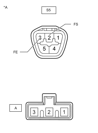
*a Component without harness connected
(Fuel Tank Vent Tube Assembly)
-
Measure the resistance according to the value(s) in the table below.
Standard Resistance Tester Connection Condition Specified Condition S5-2 (FS) - A-2 Always Below 1 Ω S5-3 (FE) - A-1 Always Below 1 Ω Result Proceed to OK NG
OK
REPLACE COMBINATION METER ASSEMBLY Click here
NG
REPLACE FUEL TANK VENT TUBE ASSEMBLY Click here
-