METER / GAUGE SYSTEM, Diagnostic DTC:B1500
| DTC Code | DTC Name |
|---|---|
| B1500 | Fuel Sender Open Detected |
DESCRIPTION
This DTC is stored when the combination meter detects a fuel sender gauge malfunction.
| DTC Code | DTC Detection Condition | Trouble Area |
|---|---|---|
| B1500 | Both conditions are met:
|
|
WIRING DIAGRAM
CAUTION / NOTICE / HINT
CAUTION:
Be careful of flames.
PROCEDURE
-
READ VALUE USING GTS (FUEL INPUT)
-
Using the GTS, read the Data List Click here.
Combination Meter Tester Display Measurement Item/Range Normal Condition Diagnostic Note Fuel Input Fuel input/Min.: 0, Max.: 127.5 Current fuel level displayed Unit: L OK Fuel amount value displayed on the GTS is almost the same as the needle indication.
OK 
REPLACE COMBINATION METER ASSEMBLY Click here
NG 
-
-
CHECK VEHICLE TYPE
-
Check the vehicle type.
Result Result Proceed to for 5 Door, Single Tank Type A for 5 Door, Double Tank Type B for 3 Door C
B 
CHECK HARNESS AND CONNECTOR (FUEL GAUGE CIRCUIT) Click here
C
CHECK HARNESS AND CONNECTOR (FUEL GAUGE CIRCUIT) Click here
A
-
-
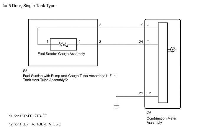
CHECK HARNESS AND CONNECTOR (FUEL GAUGE CIRCUIT)
-
Disconnect the G6 combination meter assembly connector.
-
Disconnect the S5 fuel suction with pump and gauge tube assembly*1 or fuel tank vent tube assembly*2 connector.
-
*1: for 1GR-FE, 2TR-FE
-
*2: for 1KD-FTV, 1GD-FTV, 5L-E
-
-
Measure the resistance according to the value(s) in the table below.
Standard Resistance Tester Connection Condition Specified Condition G6-9 (L) - S5-2 Always Below 1 Ω G6-24 (E) - S5-3 Always Below 1 Ω G6-21 (E2) - Body ground Always Below 1 Ω G6-9 (L) or S5-2 - Body ground Always 10 kΩ or higher G6-24 (E) or S5-3 - Body ground Always 10 kΩ or higher Result Result Proceed to OK (for 1GR-FE, 2TR-FE) A OK (for 1KD-FTV, 1GD-FTV, 5L-E) B NG C
B
INSPECT FUEL TANK VENT TUBE ASSEMBLY Click here
C
REPAIR OR REPLACE HARNESS OR CONNECTOR
A
-
-
INSPECT FUEL SUCTION WITH PUMP AND GAUGE TUBE ASSEMBLY
-
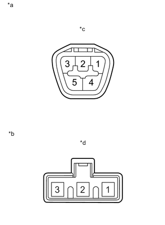
Text in Illustration *a Component without harness connected
(Fuel Suction With Pump and Gauge Tube Assembly)
*b Lower side
(to Fuel Sender Gauge Assembly)
*c Connector A *d Connector B Remove the fuel suction with pump and gauge tube assembly.
-
for 1GR-FE: Click here
-
for 2TR-FE: Click here
-
-
Measure the resistance according to the value(s) in the table below.
Standard Resistance Tester Connection Condition Specified Condition A-2 - B-1 Always Below 1 Ω A-3 - B-2 Always Below 1 Ω Result Result Proceed to OK A NG (for 1GR-FE) B NG (for 2TR-FE) C
B
REPLACE FUEL SUCTION WITH PUMP AND GAUGE TUBE ASSEMBLY Click here
C
REPLACE FUEL SUCTION WITH PUMP AND GAUGE TUBE ASSEMBLY Click here
A
-
-
INSPECT FUEL SENDER GAUGE ASSEMBLY
-
Remove the fuel sender gauge assembly.
-
for 1GR-FE: Click here
-
for 2TR-FE: Click here
-
-
Inspect the fuel sender gauge assembly.
-
for 1GR-FE: Click here
-
for 2TR-FE: Click here
Result Result Proceed to OK A NG (for 1GR-FE) B NG (for 2TR-FE) C -
A
REPLACE COMBINATION METER ASSEMBLY Click here
B
REPLACE FUEL SENDER GAUGE ASSEMBLY Click here
C
REPLACE FUEL SENDER GAUGE ASSEMBLY Click here
-
-
INSPECT FUEL TANK VENT TUBE ASSEMBLY
-
Text in Illustration *a Component without harness connected
(Fuel Tank Vent Tube Assembly)
*b Lower side
(to Fuel Sender Gauge Assembly)
*c Connector A *d Connector B Remove the fuel tank vent tube assembly.
-
for 1KD-FTV: Click here
-
for 1GD-FTV: Click here
-
for 5L-E: Click here
-
-
Measure the resistance according to the value(s) in the table below.
Standard Resistance Tester Connection Condition Specified Condition A-2 - B-1 Always Below 1 Ω A-3 - B-2 Always Below 1 Ω Result Result Proceed to OK A NG (for 1KD-FTV) B NG (for 1GD-FTV) C NG (for 5L-E) D
B
REPLACE FUEL TANK VENT TUBE ASSEMBLY Click here
C
REPLACE FUEL TANK VENT TUBE ASSEMBLY Click here
D
REPLACE FUEL TANK VENT TUBE ASSEMBLY Click here
A
-
-
INSPECT FUEL SENDER GAUGE ASSEMBLY
-
Remove the fuel sender gauge assembly.
-
for 1KD-FTV: Click here
-
for 1GD-FTV: Click here
-
for 5L-E: Click here
-
-
Inspect the fuel sender gauge assembly.
-
for 1KD-FTV: Click here
-
for 1GD-FTV: Click here
-
for 5L-E: Click here
Result Result Proceed to OK A NG (for 1KD-FTV) B NG (for 1GD-FTV) C NG (for 5L-E) D -
A
REPLACE COMBINATION METER ASSEMBLY Click here
B
REPLACE FUEL SENDER GAUGE ASSEMBLY Click here
C
REPLACE FUEL SENDER GAUGE ASSEMBLY Click here
D
REPLACE FUEL SENDER GAUGE ASSEMBLY Click here
-
-
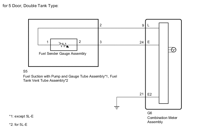
CHECK HARNESS AND CONNECTOR (FUEL GAUGE CIRCUIT)
-
Disconnect the G6 combination meter assembly connector.
-
Disconnect the S5 fuel suction with pump and gauge tube assembly*1 or fuel tank vent tube assembly*2 connector.
-
*1: except 5L-E
-
*2: for 5L-E
-
-
Measure the resistance according to the value(s) in the table below.
Standard Resistance Tester Connection Condition Specified Condition G6-9 (L) - S5-2 Always Below 1 Ω G6-24 (E) - S5-3 Always Below 1 Ω G6-21 (E2) - Body ground Always Below 1 Ω G6-9 (L) or S5-2 - Body ground Always 10 kΩ or higher G6-24 (E) or S5-3 - Body ground Always 10 kΩ or higher Result Result Proceed to OK (except 5L-E) A OK (for 5L-E) B NG C
B
INSPECT FUEL TANK VENT TUBE ASSEMBLY Click here
C
REPAIR OR REPLACE HARNESS OR CONNECTOR
A
-
-
INSPECT FUEL SUCTION WITH PUMP AND GAUGE TUBE ASSEMBLY
-
Text in Illustration *a Component without harness connected
(Fuel Suction With Pump and Gauge Tube Assembly)
*b Lower side
(to Fuel Sender Gauge Assembly)
*c Connector A *d Connector B Remove the fuel suction with pump and gauge tube assembly.
-
for 1GR-FE: Click here
-
for 2TR-FE: Click here
-
for 1KD-FTV: Click here
-
for 1GD-FTV: Click here
-
-
Measure the resistance according to the value(s) in the table below.
Standard Resistance Tester Connection Condition Specified Condition A-3 - B-1 Always Below 1 Ω A-1 - B-2 Always Below 1 Ω Result Result Proceed to OK A NG (for 1GR-FE) B NG (for 2TR-FE) C NG (for 1KD-FTV) D NG (for 1GD-FTV) E
B
REPLACE FUEL SUCTION WITH PUMP AND GAUGE TUBE ASSEMBLY Click here
C
REPLACE FUEL SUCTION WITH PUMP AND GAUGE TUBE ASSEMBLY Click here
D
REPLACE FUEL SUCTION WITH PUMP AND GAUGE TUBE ASSEMBLY Click here
E
REPLACE FUEL SUCTION WITH PUMP AND GAUGE TUBE ASSEMBLY Click here
A
-
-
INSPECT FUEL SENDER GAUGE ASSEMBLY
-
Remove the fuel sender gauge assembly.
-
for 1GR-FE: Click here
-
for 2TR-FE: Click here
-
for 1KD-FTV: Click here
-
for 1GD-FTV: Click here
-
-
Inspect the fuel sender gauge assembly.
-
for 1GR-FE: Click here
-
for 2TR-FE: Click here
-
for 1KD-FTV: Click here
-
for 1GD-FTV: Click here
Result Result Proceed to OK A NG (for 1GR-FE) B NG (for 2TR-FE) C NG (for 1KD-FTV) D NG (for 1GD-FTV) E -
A
REPLACE COMBINATION METER ASSEMBLY Click here
B
REPLACE FUEL SENDER GAUGE ASSEMBLY Click here
C
REPLACE FUEL SENDER GAUGE ASSEMBLY Click here
D
REPLACE FUEL SENDER GAUGE ASSEMBLY Click here
E
REPLACE FUEL SENDER GAUGE ASSEMBLY Click here
-
-
INSPECT FUEL TANK VENT TUBE ASSEMBLY
-
Text in Illustration *a Component without harness connected
(Fuel Tank Vent Tube Assembly)
*b Lower side
(to Fuel Sender Gauge Assembly)
*c Connector A *d Connector B Remove the fuel tank vent tube assembly Click here.
-
Measure the resistance according to the value(s) in the table below.
Standard Resistance Tester Connection Condition Specified Condition A-2 (FS) - B-2 Always Below 1 Ω A-3 (FE) - B-1 Always Below 1 Ω
NG
REPLACE FUEL TANK VENT TUBE ASSEMBLY Click here
OK
-
-
INSPECT FUEL SENDER GAUGE ASSEMBLY
-
Remove the fuel sender gauge assembly Click here.
-
Inspect the fuel sender gauge assembly Click here.
OK
REPLACE COMBINATION METER ASSEMBLY Click here
NG
REPLACE FUEL SENDER GAUGE ASSEMBLY Click here
-
-
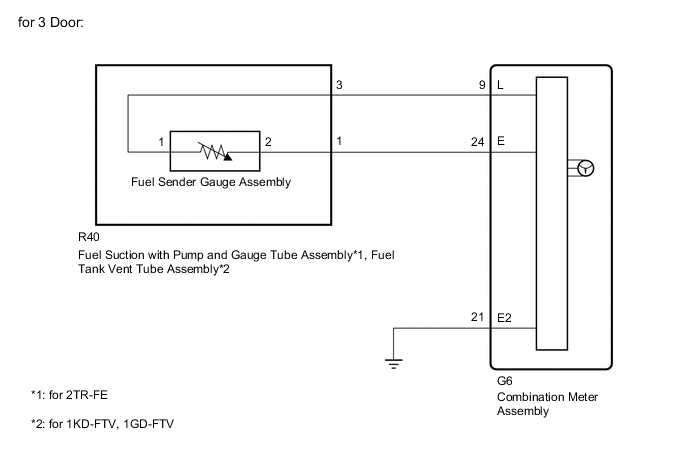
CHECK HARNESS AND CONNECTOR (FUEL GAUGE CIRCUIT)
-
Disconnect the G6 combination meter assembly connector.
-
Disconnect the R40 fuel suction with pump and gauge tube assembly*1 or fuel tank vent tube assembly*2 connector.
-
*1: for 2TR-FE
-
*2: for 1KD-FTV, 1GD-FTV
-
-
Measure the resistance according to the value(s) in the table below.
Standard Resistance Tester Connection Condition Specified Condition G6-9 (L) - R40-3 Always Below 1 Ω G6-24 (E) - R40-1 Always Below 1 Ω G6-21 (E2) - Body ground Always Below 1 Ω G6-9 (L) or R40-3 - Body ground Always 10 kΩ or higher G6-24 (E) or R40-1 - Body ground Always 10 kΩ or higher Result Result Proceed to OK (for 2TR-FE) A OK (for 1KD-FTV, 1GD-FTV) B NG C
B
INSPECT FUEL TANK VENT TUBE ASSEMBLY Click here
C
REPAIR OR REPLACE HARNESS OR CONNECTOR
A
-
-
INSPECT FUEL SUCTION WITH PUMP AND GAUGE TUBE ASSEMBLY
-
Text in Illustration *a Component without harness connected
(Fuel Suction with Pump and Gauge Tube Assembly)
*b Lower side
(to Fuel Sender Gauge Assembly)
*c Connector A *d Connector B Remove the fuel suction with pump and gauge tube assembly Click here.
-
Measure the resistance according to the value(s) in the table below.
Standard Resistance Tester Connection Condition Specified Condition A-2 (FS) - B-2 Always Below 1 Ω A-3 (FE) - B-1 Always Below 1 Ω
NG
REPLACE FUEL SUCTION WITH PUMP AND GAUGE TUBE ASSEMBLY Click here
OK
-
-
INSPECT FUEL SENDER GAUGE ASSEMBLY
-
Remove the fuel sender gauge assembly Click here.
-
Inspect the fuel sender gauge assembly Click here.
OK
REPLACE COMBINATION METER ASSEMBLY Click here
NG
REPLACE FUEL SENDER GAUGE ASSEMBLY Click here
-
-
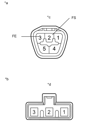
INSPECT FUEL TANK VENT TUBE ASSEMBLY
-
Text in Illustration *a Component without harness connected
(Fuel Tank Vent Tube Assembly)
*b Lower side
(to Fuel Sender Gauge Assembly)
*c Connector A *d Connector B Remove the fuel tank vent tube assembly.
-
for 1KD-FTV: Click here
-
for 1GD-FTV: Click here
-
-
Measure the resistance according to the value(s) in the table below.
Standard Resistance Tester Connection Condition Specified Condition A-2 (FS) - B-2 Always Below 1 Ω A-3 (FE) - B-1 Always Below 1 Ω Result Result Proceed to OK A NG (for 1KD-FTV) B NG (for 1GD-FTV) C
B
REPLACE FUEL TANK VENT TUBE ASSEMBLY Click here
C
REPLACE FUEL TANK VENT TUBE ASSEMBLY Click here
A
-
-
INSPECT FUEL SENDER GAUGE ASSEMBLY
-
Remove the fuel sender gauge assembly.
-
for 1KD-FTV: Click here
-
for 1GD-FTV: Click here
-
-
Inspect the fuel sender gauge assembly.
-
for 1KD-FTV: Click here
-
for 1GD-FTV: Click here
Result Result Proceed to OK A NG (for 1KD-FTV) B NG (for 1GD-FTV) C -
A
REPLACE COMBINATION METER ASSEMBLY Click here
B
REPLACE FUEL SENDER GAUGE ASSEMBLY Click here
C
REPLACE FUEL SENDER GAUGE ASSEMBLY Click here
-