METER / GAUGE SYSTEM Meter Illumination does not Dim at Night
DESCRIPTION
If the dimmer switch is turned to TAIL, HEAD or AUTO, the main body ECU sends a TAIL relay signal, panel light illumination signal, panel relay signal, and TAIL cancel OFF signal to the combination meter. Then the meter dims.
Tech Tips
TAIL cancel switch: When the headlights are illuminated and the TAIL cancel switch is turned ON, the meter does not dim.
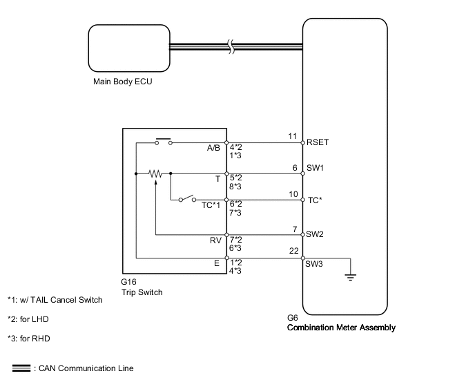
WIRING DIAGRAM
PROCEDURE
-
CHECK CAN COMMUNICATION SYSTEM
-
Check if a CAN communication DTC is output.
-
for LHD with Entry and Start System Click here.
-
for LHD without Entry and Start System Click here.
-
for RHD with Entry and Start System Click here.
-
for RHD without Entry and Start System Click here.
Result Result Proceed to CAN communication system DTC is not output A CAN communication system DTC is output (for LHD with Entry and Start System) B CAN communication system DTC is output (for LHD without Entry and Start System) C CAN communication system DTC is output (for RHD with Entry and Start System) D CAN communication system DTC is output (for RHD without Entry and Start System) E
-
B 
GO TO CAN COMMUNICATION SYSTEM Click here
C
GO TO CAN COMMUNICATION SYSTEM Click here
D
GO TO CAN COMMUNICATION SYSTEM Click here
E
GO TO CAN COMMUNICATION SYSTEM Click here
A 
-
-
READ VALUE USING GTS (TAIL CANCEL SW, RHEOSTAT VALUE)
-
Using the GTS, read the Data List Click here.
Combination Meter Tester Display Measurement Item/Range Normal Condition Diagnostic Note Tail Cancel SW* Tail cancel switch/OFF or ON OFF: Tail cancel switch off - ON: Tail cancel switch on Rheostat value Light control rheostat switch input/Min.: 0, Max.: 100 Light control rheostat switch is fully turned right (0) → fully turned left (100) Unit: %
-
*: w/ TAIL Cancel Switch
OK Light brightness can be changed within specified range by manual operation. -
OK
REPLACE COMBINATION METER ASSEMBLY Click here
NG
-
-
INSPECT TRIP SWITCH (LIGHT CONTROL RHEOSTAT)
-
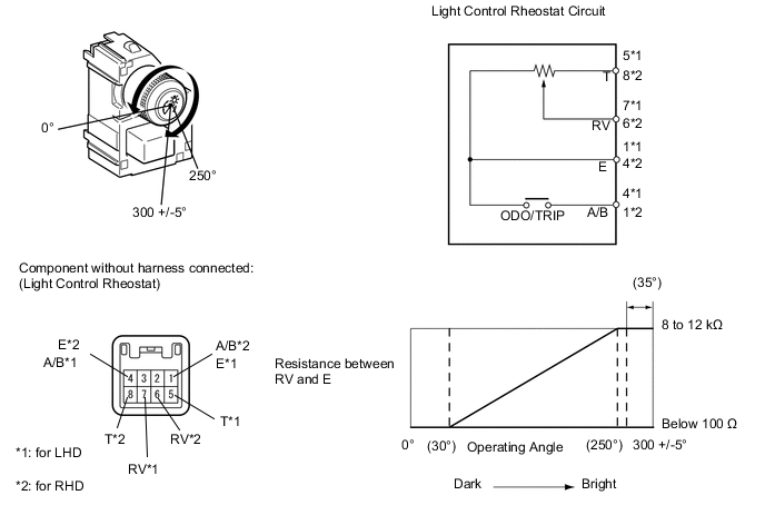
Inspect the light control rheostat. (w/o TAIL cancel switch)
-
Remove the light control rheostat Click here.
-
Measure the resistance according to the value(s) in the table below.
Standard Resistance for LHD Tester Connection Switch Condition Specified Condition 5 (T) - 1 (E) Always 8 to 12 kΩ 7 (RV) - 1 (E) Light control rheostat fully turned right → fully turned left Below 100 Ω → 8 to 12 kΩ for RHD Tester Connection Switch Condition Specified Condition 8 (T) - 4 (E) Always 8 to 12 kΩ 6 (RV) - 4 (E) Light control rheostat fully turned right → fully turned left Below 100 Ω → 8 to 12 kΩ
-
-
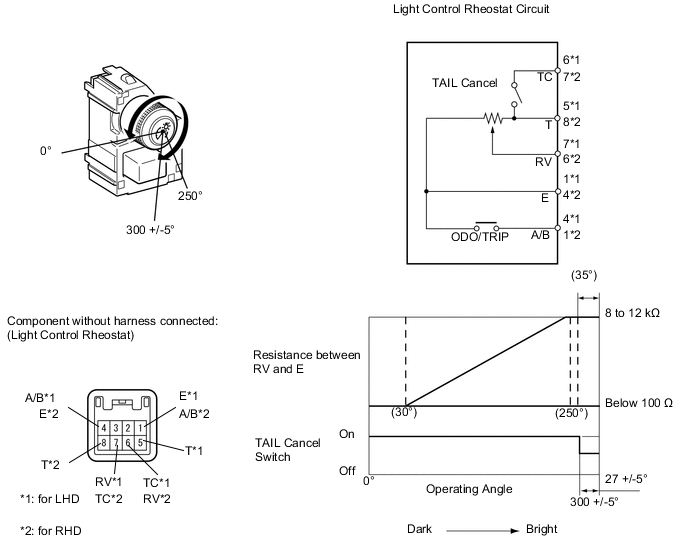
Inspect the light control rheostat. (w/ TAIL cancel switch)
-
Remove the light control rheostat Click here.
-
Measure the resistance according to the value(s) in the table below.
Standard Resistance for LHD Tester Connection Switch Condition Specified Condition 5 (T) - 6 (TC) TAIL cancel switch off → on 1 MΩ or higher → Below 1 Ω 5 (T) - 1 (E) Always 8 to 12 kΩ 7 (RV) - 1 (E) Light control rheostat fully turned right → fully turned left Below 100 Ω → 8 to 12 kΩ for RHD Tester Connection Switch Condition Specified Condition 8 (T) - 7 (TC) TAIL cancel switch off → on 1 MΩ or higher → Below 1 Ω 8 (T) - 4 (E) Always 8 to 12 kΩ 6 (RV) - 4 (E) Light control rheostat fully turned right → fully turned left Below 100 Ω → 8 to 12 kΩ
-
NG
REPLACE TRIP SWITCH (LIGHT CONTROL RHEOSTAT) Click here
OK
-
-
CHECK HARNESS AND CONNECTOR (COMBINATION METER ASSEMBLY - TRIP SWITCH [LIGHT CONTROL RHEOSTAT])
-
Disconnect the G6 combination meter assembly connector.
-
Disconnect the G16 trip switch (light control rheostat) connector.
-
Measure the resistance according to the value(s) in the table below.
Standard Resistance for LHD Tester Connection Condition Specified Condition G6-10 (TC) - G16-6 (TC)* Always Below 1 Ω G6-6 (SW1) - G16-5 (T) Always Below 1 Ω G6-7 (SW2) - G16-7 (RV) Always Below 1 Ω G6-22 (SW3) - G16-1 (E) Always Below 1 Ω for RHD Tester Connection Condition Specified Condition G6-10 (TC) - G16-7 (TC)* Always Below 1 Ω G6-6 (SW1) - G16-8 (T) Always Below 1 Ω G6-7 (SW2) - G16-6 (RV) Always Below 1 Ω G6-22 (SW3) - G16-4 (E) Always Below 1 Ω G6-22 (SW3) - G16-4 (E) Always Below 1 Ω
-
*: w/ TAIL Cancel Switch
-
OK
REPLACE COMBINATION METER ASSEMBLY Click here
NG
REPAIR OR REPLACE HARNESS OR CONNECTOR
-