METER / GAUGE SYSTEM Odo/Trip Switch Malfunction
DESCRIPTION
The meter CPU receives ODO/TRIP change switch signal from the light control rheostat via the direct line.
Tech Tips
The whole light control rheostat should be replaced if the ODO/TRIP switch is malfunctioning.
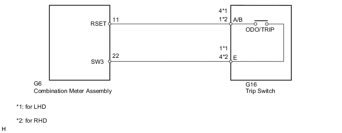
WIRING DIAGRAM
PROCEDURE
-
READ VALUE USING GTS (ODO/TRIP CHANGE SW)
-
Using the GTS, read the Data List Click here.
Combination Meter Tester Display Measurement Item/Range Normal Condition Diagnostic Note ODO/TRIP Change SW ODO/TRIP change switch/OFF or ON OFF: ODO/TRIP change switch released - ON: ODO/TRIP change switch pressed OK The value displayed on the GTS changes with the actual ODO/TRIP change switch operation.
OK 
REPLACE COMBINATION METER ASSEMBLY Click here
NG 
-
-
INSPECT TRIP SWITCH
-
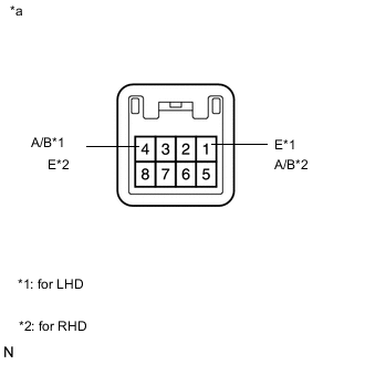
Disconnect the G16 trip switch connector.
-
Inspect the ODO/TRIP switch
-
Measure the resistance according to the value(s) in the table below.
Standard Resistance for LHD Tester Connection Switch Condition Specified Condition 4 (A/B) - 1 (E) ODO/TRIP switch on (pushed) Below 1 Ω ODO/TRIP switch off (Not pushed) 1 MΩ or higher for RHD Tester Connection Switch Condition Specified Condition 1 (A/B) - 4 (E) ODO/TRIP switch on (pushed) Below 1 Ω ODO/TRIP switch off (Not pushed) 1 MΩ or higher
-
NG
REPLACE TRIP SWITCH Click here
OK
-
-
CHECK HARNESS AND CONNECTOR (COMBINATION METER ASSEMBLY - TRIP SWITCH)
-
Disconnect the G6 combination meter assembly connector.
-
Disconnect the G16 trip switch connector.
-
Measure the resistance according to the value(s) in the table below.
Standard Resistance for LHD Tester Connection Condition Specified Condition G6-11 (RSET) - G16-4 (A/B) Always Below 1 Ω G6-11 (RSET) - Body ground Always 10 kΩ or higher for RHD Tester Connection Condition Specified Condition G6-11 (RSET) - G16-1 (A/B) Always Below 1 Ω G6-11 (RSET) - Body ground Always 10 kΩ or higher
OK
REPLACE COMBINATION METER ASSEMBLY Click here
NG
REPAIR OR REPLACE HARNESS OR CONNECTOR
-