ENGINE UNIT DISASSEMBLY

PROCEDURE
-
REMOVE SPARK PLUG
-
REMOVE OIL FILLER CAP SUB-ASSEMBLY
-
Remove the oil filler cap sub-assembly.
-
Remove the gasket from the oil filler cap sub-assembly.
-
-
REMOVE PCV VALVE SUB-ASSEMBLY
-
REMOVE CAMSHAFT POSITION SENSOR (for Intake Side)
-
REMOVE CAMSHAFT POSITION SENSOR (for Exhaust Side)
-
REMOVE CRANKSHAFT POSITION SENSOR
-
REMOVE CAMSHAFT TIMING OIL CONTROL VALVE ASSEMBLY (for Intake Side)
-
REMOVE CAMSHAFT TIMING OIL CONTROL VALVE ASSEMBLY (for Exhaust Side)
-
REMOVE CYLINDER HEAD COVER SUB-ASSEMBLY
-
REMOVE NO. 1 VENTILATION CONNECTOR
-
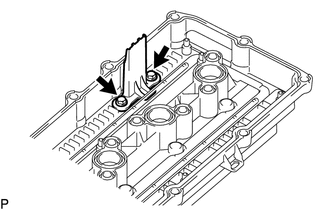
Remove the 2 bolts and No. 1 ventilation connector from the cylinder head cover sub-assembly.
-
-
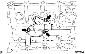
REMOVE WATER INLET
-
REMOVE THERMOSTAT
-
REMOVE CRANKSHAFT PULLEY
-
REMOVE OIL PAN COVER SILENCER
-
REMOVE NO. 2 OIL PAN SUB-ASSEMBLY
-
REMOVE OIL PAN SUB-ASSEMBLY
-
REMOVE OIL STRAINER SUB-ASSEMBLY
-
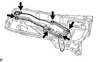
Remove the 6 bolts, oil strainer sub-assembly and gasket.
-
-
REMOVE OIL PAN STUD BOLT
Note
If a stud bolt is deformed or its threads are damaged, replace it.
-
REMOVE REAR ENGINE OIL SEAL RETAINER
-
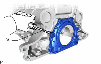
Text in Illustration *a Protective Tape Remove the 6 bolts.
-
Using a screwdriver, pry out the rear engine oil seal retainer.
Tech Tips
Tape the screwdriver tip before use.
-
-
REMOVE REAR ENGINE OIL SEAL
-
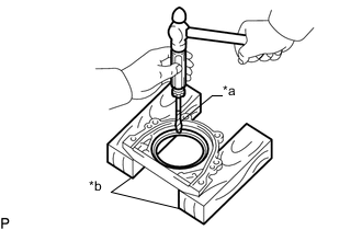
Text in Illustration *a Protective Tape *b Wooden Blocks Place the rear engine oil seal retainer on wooden blocks.
-
Using a screwdriver and hammer, tap out the rear engine oil seal.
Tech Tips
Tape the screwdriver tip before use.
-
-
REMOVE ENGINE OIL PRESSURE SWITCH ASSEMBLY
-
REMOVE KNOCK SENSOR
-
REMOVE ENGINE COOLANT TEMPERATURE SENSOR
-
REMOVE OIL FILTER SUB-ASSEMBLY
-
REMOVE NO. 4 WATER BY-PASS HOSE (w/ Oil Cooler)
-
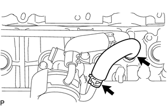
Slide the 2 clips and remove the No. 4 water by-pass hose from the oil cooler assembly and union.
-
-
REMOVE NO. 4 WATER BY-PASS PIPE (w/ Oil Cooler)
-
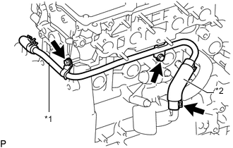
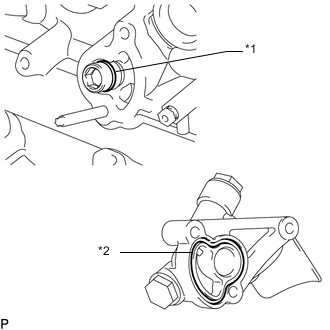
Text in Illustration *1 No. 4 Water By-pass Pipe *2 No. 5 Water By-pass Hose Disconnect the No. 5 water by-pass hose from the oil cooler assembly.
-
Remove the 2 bolts and No. 4 water by-pass pipe.
-
-
REMOVE OIL COOLER ASSEMBLY (w/ Oil Cooler)
-
REMOVE OIL FILTER UNION (w/o Oil Cooler)
-
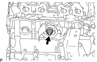
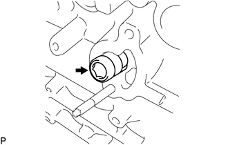
Using a 27 mm socket wrench, remove the oil filter union.
-
-
REMOVE OIL FILTER BRACKET SUB-ASSEMBLY
-
Remove the 2 bolts and nut from the oil filter bracket.
-
Remove the 2 screw plugs and 2 gaskets from the oil filter bracket.
-
Text in Illustration *1 O-Ring *2 Oil Filter Bracket Gasket Remove the oil filter bracket gasket and O-ring.
-
Using a hexagon wrench, remove the oil filter bracket union.
-
-
REMOVE UNION (w/ Oil Cooler)
-
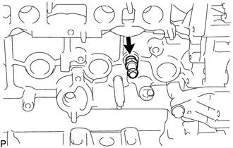
Remove the union from the cylinder block.
-
-
REMOVE NO. 1 TAPER SCREW PLUG (w/o Oil Cooler)
-
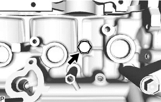
Remove the No. 1 taper screw plug from the cylinder block.
-
-
REMOVE V-RIBBED BELT TENSIONER ASSEMBLY
-
REMOVE TIMING CHAIN COVER SUB-ASSEMBLY
-
REMOVE ENGINE WATER PUMP ASSEMBLY
-
REMOVE TIMING CHAIN CASE OIL SEAL
-
SET NO. 1 CYLINDER TO TDC/COMPRESSION
-
Temporarily install the crankshaft pulley bolt.
-
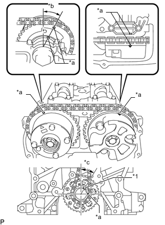
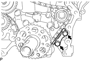
Text in Illustration *1 Crankshaft Pulley Set Key *a Timing Mark *b Approximately 13° *c Approximately 30° Rotate the crankshaft clockwise so that the timing marks on the crankshaft timing gear and camshaft timing gears are as shown in the illustration.
Tech Tips
If the timing marks do not align, rotate the crankshaft clockwise again and align the timing marks.
-
Remove the crankshaft pulley bolt.
-
-
REMOVE CYLINDER HEAD COVER CONNECTOR SUB-ASSEMBLY
-
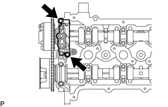
Remove the 2 bolts and cylinder head cover connector sub-assembly.
-
Remove the No. 2 camshaft bearing cap oil hole gasket and 3 No. 3 camshaft bearing cap oil hole gaskets from the No. 1 camshaft bearing cap.
-
-
REMOVE TIMING CHAIN GUIDE
-
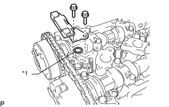
Text in Illustration *1 O-Ring Remove the 2 bolts, timing chain guide and O-ring.
-
-
REMOVE NO. 1 CHAIN TENSIONER ASSEMBLY
Note
-
When the No. 1 chain tensioner assembly is removed, do not rotate the crankshaft.
-
When the chain is removed and the camshaft needs to be rotated, rotate the crankshaft 90° to the right.
-
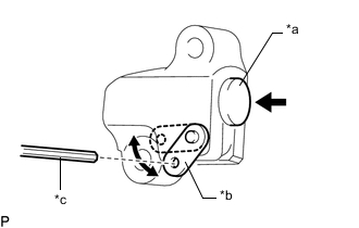
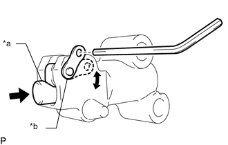
Text in Illustration *a Plunger *b Stopper Plate *c Hexagon Wrench Move the stopper plate upward to release the lock and push the plunger deep into the tensioner.
-
Move the stopper plate downward to set the lock and insert a hexagon wrench into the stopper plate hole.
-
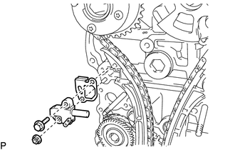
Remove the bolt, nut, No. 1 chain tensioner assembly and gasket.
-
-
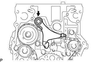
REMOVE CHAIN TENSIONER SLIPPER
-
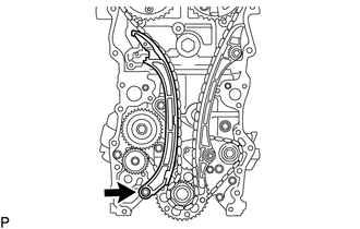
Remove the bolt and chain tensioner slipper.
-
-
REMOVE NO. 1 CHAIN VIBRATION DAMPER
-
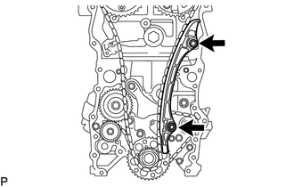
Remove the bolt, nut and No. 1 chain vibration damper.
-
-
REMOVE CHAIN SUB-ASSEMBLY
-
REMOVE CRANKSHAFT TIMING GEAR OR SPROCKET
-
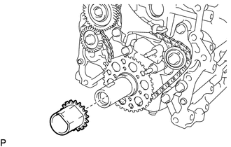
Remove the crankshaft timing gear or sprocket from the crankshaft.
-
-
REMOVE CAMSHAFT BEARING CAP
-
REMOVE CAMSHAFT
-
REMOVE NO. 2 CAMSHAFT
-
REMOVE NO. 1 VALVE ROCKER ARM SUB-ASSEMBLY
-
REMOVE VALVE LASH ADJUSTER ASSEMBLY
-
REMOVE VALVE STEM CAP
-
INSPECT CAMSHAFT TIMING GEAR ASSEMBLY
-
REMOVE CAMSHAFT TIMING GEAR ASSEMBLY
-
INSPECT CAMSHAFT TIMING EXHAUST GEAR ASSEMBLY
-
REMOVE CAMSHAFT TIMING EXHAUST GEAR ASSEMBLY
-
REMOVE CYLINDER HEAD SUB-ASSEMBLY
-
REMOVE CYLINDER HEAD GASKET
-
REMOVE OIL CONTROL VALVE FILTER
-
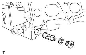
Using an 8 mm hexagon wrench, remove the screw plug.
-
Remove the oil control valve filter and gasket.
-
-
REMOVE NO. 2 CHAIN VIBRATION DAMPER
-
Text in Illustration *a Plunger *b Stopper Plate Move the stopper plate downward to release the lock and push the plunger deep into the tensioner.
-
Move the stopper plate upward to set the lock and insert a hexagon wrench into the stopper plate hole.
-
Remove the bolt and No. 2 chain vibration damper.
-
-
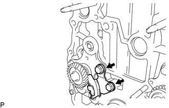
REMOVE NO. 3 CHAIN VIBRATION DAMPER
-
Remove the 2 bolts and No. 3 chain vibration damper.
-
-
REMOVE NO. 2 CHAIN TENSIONER ASSEMBLY
-
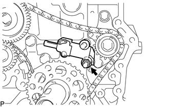
Remove the hexagon wrench from the No. 2 chain tensioner assembly.
-
Remove the nut and No. 2 chain tensioner assembly.
-
-
REMOVE NO. 2 CHAIN SUB-ASSEMBLY
-
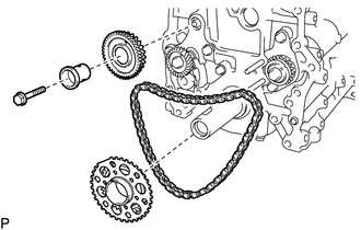
Remove the bolt, balanceshaft drive gear shaft and balanceshaft drive gear sub-assembly.
-
Remove the crankshaft timing sprocket and No. 2 chain sub-assembly.
-
-
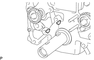
REMOVE NO. 4 CHAIN VIBRATION DAMPER
-
Remove the 2 bolts and No. 4 chain vibration damper.
-
-
REMOVE CRANKSHAFT PULLEY SET KEY
-
Remove the 2 crankshaft pulley set keys from the crankshaft.
-