CAMSHAFT INSTALLATION

CAUTION / NOTICE / HINT
Tech Tips
Perform "Inspection After Repairs" after replacing the camshaft, No. 2 camshaft, camshaft timing gear assembly or camshaft timing exhaust gear assembly Click here.
PROCEDURE
-
INSTALL CAMSHAFT TIMING EXHAUST GEAR ASSEMBLY
Tech Tips
Perform "Inspection After Repairs" after replacing the camshaft timing exhaust gear assembly Click here.
-
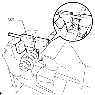
Text in Illustration *a Hexagonal Portion Using SST, grip the hexagonal portion, and then secure SST and No. 2 camshaft in a vise as shown in the illustration.
- SST
- 09212-31010
Note
-
Do not damage the No. 2 camshaft.
-
Never grip areas other than the hexagonal portion, as this may cause damage.
-
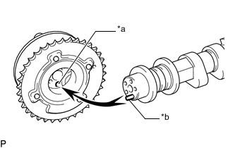
Text in Illustration *a Straight Pin Hole *b Straight Pin Align and attach the straight pin of the No. 2 camshaft with the straight pin hole of the camshaft timing exhaust gear assembly.
-
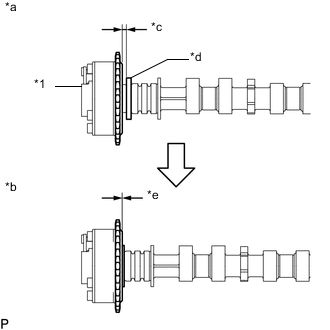
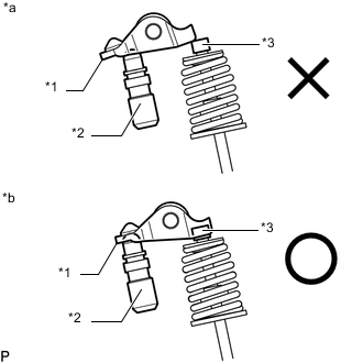
Text in Illustration *1 Camshaft Timing Exhaust Gear Assembly *a INCORRECT *b CORRECT *c Clearance *d Camshaft Flange *e No Clearance Check that there is no clearance between the camshaft timing exhaust gear assembly and camshaft flange.
Note
Be sure not to remove the other 4 bolts. If removing the bolts, exchange the camshaft timing exhaust gear assembly.
-
Fix the camshaft timing exhaust gear assembly with the flange bolt.
- Torque:
- 78 N*m { 795 kgf*cm, 58 ft.*lbf }
-
-
INSTALL CAMSHAFT TIMING GEAR ASSEMBLY
Tech Tips
Perform "Inspection After Repairs" after replacing the camshaft timing gear assembly Click here.
-
Text in Illustration *a Hexagonal Portion Using SST, grip the hexagonal portion, and then secure SST and camshaft in a vise as shown in the illustration.
- SST
- 09212-31010
Note
-
Do not damage the camshaft.
-
Never grip areas other than the hexagonal portion, as this may cause damage.
-
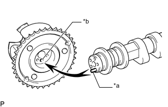
Text in Illustration *a Straight Pin *b Straight Pin Hole Align the straight pin hole and straight pin and install the camshaft timing gear assembly to the camshaft.
-
Lightly press the gear against the camshaft and turn the gear. Push further at the position where the straight pin enters the straight pin hole.
Note
Be sure not to turn the camshaft timing gear assembly in the retard direction (the right angle).
-
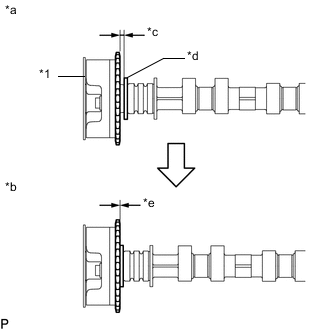
Text in Illustration *1 Camshaft Timing Gear Assembly *a INCORRECT *b CORRECT *c Clearance *d Camshaft Flange *e No Clearance Check that there is no clearance between the camshaft timing gear assembly and the flange of the camshaft.
Note
-
Since the thrust clearance of the camshaft is small, the camshaft must be kept level while it is being removed. If the camshaft is not kept level, the portion of the cylinder head receiving the shaft thrust may crack or be damaged, causing the camshaft to seize or break.
-
Be sure not to remove the other 3 bolts. If removing the bolts, exchange the camshaft timing gear assembly.
-
-
With the camshaft timing gear assembly fixed in place, install the flange bolt.
- Torque:
- 78 N*m { 795 kgf*cm, 58 ft.*lbf }
-
Check that the camshaft timing gear assembly can move in the retard direction (the right angle), and is locked at the most retarded position.
-
-
INSTALL CAMSHAFT AND NO. 2 CAMSHAFT
-
Apply clean engine oil to the camshaft cams and cylinder head journals.
-
Install the chain sub-assembly to the camshaft timing gear assembly with the paint mark of the link aligned with the timing mark of the camshaft timing gear assembly.
Text in Illustration *a Paint Mark *b Timing Mark -
Temporarily install the 4 No. 2 camshaft bearing caps using the 8 bolts as shown in the illustration.
-
Install the chain sub-assembly to the No. 2 camshaft, and then install the No. 2 camshaft to the cylinder head sub-assembly.
Tech Tips
Place the chain sub-assembly on the camshaft timing gear assembly but do not engage the teeth of the sprocket and the chain sub-assembly.
-
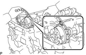
Move the camshaft in the direction shown in the illustration to loosen the chain sub-assembly, and align the paint mark on the camshaft timing gear assembly and chain sub-assembly and connect the chain sub-assembly to the camshaft timing gear assembly.
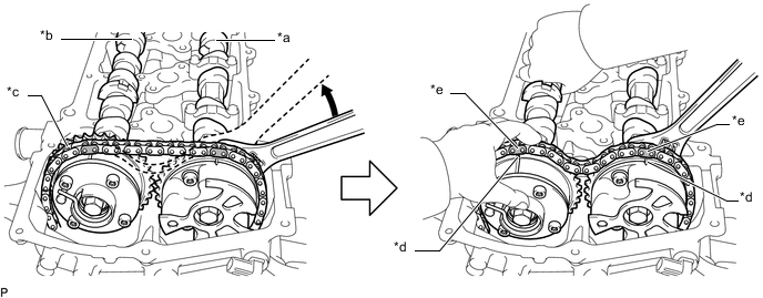
Text in Illustration *a Camshaft *b No. 2 Camshaft *c Chain Sub-assembly *d Timing Mark *e Paint Mark - - -
Text in Illustration *1 No. 1 Valve Rocker Arm Sub-assembly *2 Valve Lash Adjuster Assembly *3 Valve Stem Cap *a INCORRECT *b CORRECT Make sure that the No. 1 valve rocker arm sub-assemblies are installed as shown in the illustration.
-
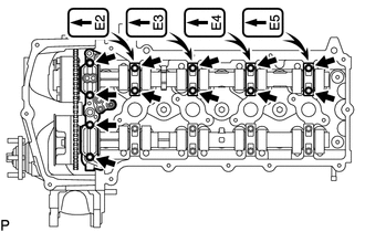
Temporarily install the No. 1 camshaft bearing cap and 4 No. 2 camshaft bearing caps using the 12 bolts.
-
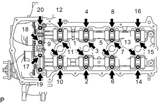
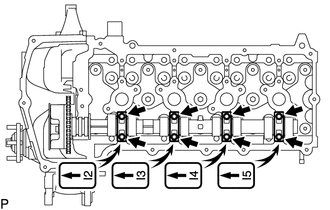
Install the 20 bolts in the order shown in the illustration.
- Torque:
- 16 N*m { 158 kgf*cm, 11 ft.*lbf }
-
-
INSTALL NO. 1 CHAIN TENSIONER ASSEMBLY
-
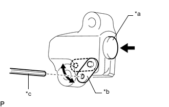
Text in Illustration *a Plunger *b Stopper Plate *c Hexagon Wrench Move the stopper plate upward to release the lock and push the plunger deep into the tensioner.
-
Move the stopper plate downward to set the lock and insert a hexagon wrench into the hole of the stopper plate.
-
Install a new gasket and the No. 1 chain tensioner assembly with the bolt and nut.
- Torque:
- 10 N*m { 102 kgf*cm, 7 ft.*lbf }
Note
Remove the hexagon wrench after installing the timing chain guide.
-
Install a new gasket to the timing chain cover plate.
-
Install the timing chain cover plate to the timing chain cover sub-assembly with the 2 bolts.
- Torque:
- 9.0 N*m { 92 kgf*cm, 80 in.*lbf }
-
-
CHECK NO. 1 CYLINDER TO TDC/COMPRESSION
-
Check that the No. 1 cylinder is set to TDC/compression.
-
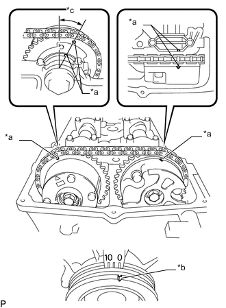
Text in Illustration *a Timing Mark *b Groove *c Approximately 13° Rotate the crankshaft two full rotations, and then check that all timing marks are in the position shown in the illustration.
If the timing marks do not match, set the chain sub-assembly again.
-
-
-
INSTALL TIMING CHAIN GUIDE
-
INSTALL CYLINDER HEAD COVER CONNECTOR SUB-ASSEMBLY
-
INSTALL CYLINDER HEAD COVER SUB-ASSEMBLY
-
INSTALL IGNITION COIL ASSEMBLY
-
INSTALL FAN SHROUD
-
INSTALL RADIATOR RESERVOIR
-
INSTALL INTAKE AIR CONNECTOR
-
INSTALL AIR CLEANER CAP SUB-ASSEMBLY
-
CONNECT CABLE TO NEGATIVE BATTERY TERMINAL
Note
When disconnecting the cable, some systems need to be initialized after the cable is reconnected Click here.
-
ADD ENGINE OIL
-
INSPECT FOR OIL LEAK
-
INSPECT ENGINE OIL LEVEL
-
INSPECT IGNITION TIMING
-
INSPECT ENGINE IDLE SPEED
-
INSTALL UPPER RADIATOR SUPPORT SEAL
-
INSTALL NO. 1 ENGINE UNDER COVER SUB-ASSEMBLY
-
INSTALL FRONT BUMPER COVER LOWER