CYLINDER BLOCK DISASSEMBLY

PROCEDURE
-
INSPECT CONNECTING ROD THRUST CLEARANCE
-
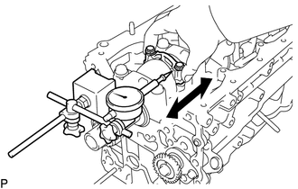
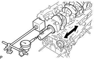
Using a dial indicator, measure the thrust clearance while moving the connecting rod back and forth.
Standard thrust clearance 0.15 to 0.35 mm (0.00591 to 0.0138 in.) Maximum thrust clearance 0.40 mm (0.0157 in.) If the thrust clearance is more than the maximum, replace the connecting rod assembly. If necessary, replace the crankshaft.
-
-
INSPECT CONNECTING ROD OIL CLEARANCE
-
Check that the matchmarks on the connecting rod and cap are aligned to ensure correct reassembly.
Tech Tips
The matchmarks on the connecting rods and caps are for ensuring correct reassembly.
-
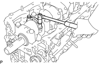
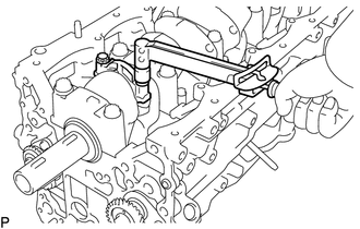
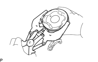
Remove the 2 connecting rod cap bolts.
-
Using the 2 removed connecting rod cap bolts, remove the connecting rod cap and lower bearing by wiggling the connecting rod cap right and left.
Tech Tips
Keep the lower bearing installed to the connecting rod cap.
-
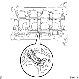
Clean the crank pin and bearing.
-
Check the crank pin and bearing for pitting and scratches.
-
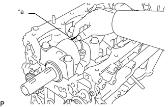
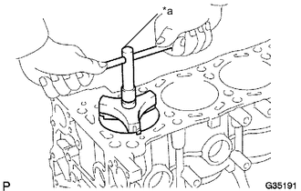
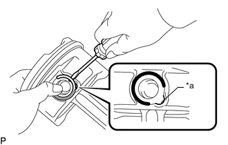
Text in Illustration *a Plastigage Lay a strip of Plastigage on the crank pin.
-
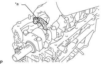
Text in Illustration *a Front Mark Check that the front mark of the connecting rod cap is facing forward.
-
Install the connecting rod cap Click here.
Note
Do not turn the crankshaft.
-
Remove the 2 bolts and connecting rod cap (refer to the steps above).
-
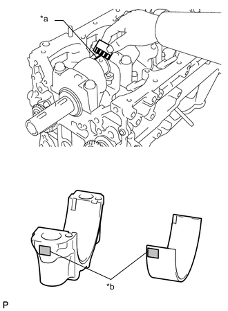
Text in Illustration *a Plastigage *b 4, 5 or 6 Mark Measure the Plastigage at its widest point.
Standard oil clearance 0.039 to 0.066 mm (0.00154 to 0.00260 in.) Maximum oil clearance 0.066 mm (0.00260 in.) If the oil clearance is more than the maximum, replace the connecting rod bearings. If necessary, inspect the crankshaft.
If replacing a bearing, replace it with one that has the same number as its respective connecting rod cap. The standard thickness of each bearing is indicated by a 4, 5 or 6 mark on its surface.
Standard crankshaft pin diameter 52.989 to 53.002 mm (2.086 to 2.087 in.) Standard Bearing Center Wall Thickness Item Specified Condition Mark 4 1.487 to 1.490 mm (0.05854 to 0.05866 in.) Mark 5 1.491 to 1.493 mm (0.05870 to 0.05878 in.) Mark 6 1.494 to 1.496 mm (0.05882 to 0.05890 in.) -
Completely remove the Plastigage.
-
Perform the inspection above for each crank pin.
-
-
REMOVE PISTON SUB-ASSEMBLY WITH CONNECTING ROD
-
Text in Illustration *a Ridge Reamer Using a ridge reamer, remove all the carbon from the top of the cylinder.
-
Push the piston, connecting rod assembly and upper bearing through the top of the cylinder block.
Tech Tips
-
Keep the bearing, connecting rod and cap together.
-
Arrange the piston and connecting rod assemblies in the correct order.
-
-
-
REMOVE CONNECTING ROD BEARING
-
Remove the connecting rod bearings from the connecting rods and connecting rod caps.
Tech Tips
Arrange the removed parts in the correct order.
-
-
INSPECT CRANKSHAFT THRUST CLEARANCE
-
Using a dial indicator, measure the thrust clearance while prying the crankshaft back and forth with a screwdriver.
Standard thrust clearance 0.02 to 0.22 mm (0.000787 to 0.00866 in.) Maximum thrust clearance 0.30 mm (0.0118 in.) If the thrust clearance is more than the maximum, replace the thrust washers as a set. If necessary, replace the crankshaft.
Thrust washer thickness 2.440 to 2.490 mm (0.0961 to 0.0980 in.)
-
-
REMOVE CRANKSHAFT
-
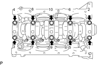
Uniformly loosen the 10 bearing cap bolts in several steps in the sequence shown in the illustration.
Tech Tips
-
Keep the lower bearings and crankshaft bearing caps together.
-
Arrange the thrust washers in the correct order.
-
-
Lift out the crankshaft to remove it.
-
Remove the upper thrust washers from the cylinder block.
Tech Tips
Arrange the main bearing caps, bearings and thrust washers in the correct order.
-
-
REMOVE CRANKSHAFT BEARING
-
Remove the crankshaft bearings from the cylinder block and bearing caps.
Tech Tips
Arrange the removed parts in the correct order.
-
-
REMOVE PISTON RING SET
-
Using a piston ring expander, remove the 2 compression rings.
-
Remove the oil ring expander and 2 oil ring side rails by hand.
Tech Tips
Arrange the piston rings in the correct order.
-
-
REMOVE PISTON WITH PIN SUB-ASSEMBLY
-
Check the fitting condition between the piston and piston pin.
-
Try to move the piston back and forth on the piston pin.
If any movement is felt, replace the piston and pin as a set.
-
-
Disconnect the connecting rod from the piston.
-
Text in Illustration *a Snap Ring Using a screwdriver, pry off the snap rings from the piston.
-
Gradually heat the piston to approximately 80 to 90°C (176 to 194°F).
-
Using a brass bar and plastic-faced hammer, lightly tap out the piston pin and remove the connecting rod.
Tech Tips
-
The piston and pin are a matched set.
-
Arrange the pistons, pins, rings, connecting rods and bearings in the correct order.
-
-
-
-
CLEAN PISTON WITH PIN SUB-ASSEMBLY
-
Using a gasket scraper, remove the carbon from the piston top.
-
Using a groove cleaning tool or broken ring, clean the piston ring grooves.
-
Using solvent and a brush, thoroughly clean the piston.
Note
Do not use a wire brush.
-
-
REMOVE NO. 1 OIL NOZZLE SUB-ASSEMBLY
-
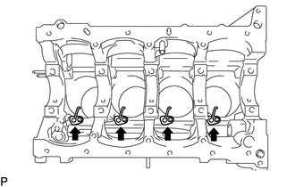
Using a 5 mm hexagon wrench, remove the oil nozzles.
-
-
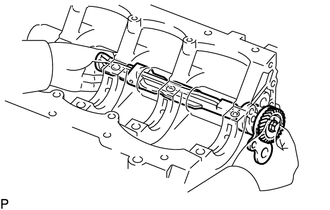
INSPECT BALANCESHAFT THRUST CLEARANCE
-
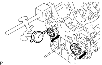
Using a dial indicator, measure the thrust clearance while moving the balanceshaft back and forth.
Standard thrust clearance 0.07 to 0.13 mm (0.00276 to 0.00512 in.) Maximum thrust clearance 0.20 mm (0.00787 in.) If the thrust clearance is more than the maximum, replace the balanceshaft thrust washer. If necessary, replace the balanceshaft.
-
-
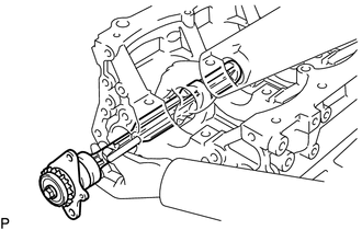
REMOVE NO. 1 BALANCESHAFT
-
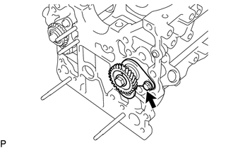
Remove the bolt.
-
Remove the balanceshaft from the cylinder block.
Note
When removing the balanceshaft, be sure to support the balanceshaft with both hands and avoid scratching the balanceshaft bearing on the cylinder block.
-
-
REMOVE NO. 1 BALANCESHAFT DRIVEN GEAR
-
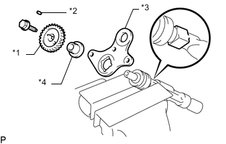
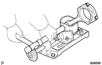
Text in Illustration *1 No. 1 Balanceshaft Driven Gear *2 Sliding Key *3 Balanceshaft Thrust Washer *4 Balanceshaft Thrust Spacer Mount the head portion of the balanceshaft in a vise.
Note
Do not damage the balanceshaft.
-
Remove the bolt.
-
Remove the No. 1 balanceshaft driven gear, sliding key, balanceshaft thrust washer and balanceshaft thrust spacer.
-
-
REMOVE NO. 2 BALANCESHAFT
-
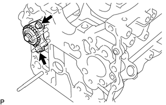
Remove the 2 bolts.
-
Remove the balanceshaft from the cylinder block.
Note
When removing the balanceshaft, be sure to support the balanceshaft with both hands and avoid scratching the balanceshaft bearing on the cylinder block.
-
-
REMOVE NO. 2 BALANCESHAFT DRIVEN GEAR
-
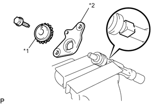
Text in Illustration *1 No. 2 Balanceshaft Driven Gear *2 No. 2 Balanceshaft Thrust Washer Mount the head portion of the balanceshaft in a vise.
Note
Do not damage the balanceshaft.
-
Remove the bolt.
-
Remove the No. 2 balanceshaft driven gear and No. 2 balanceshaft thrust washer.
-
-
REMOVE CYLINDER BLOCK WATER DRAIN COCK SUB-ASSEMBLY
-
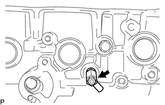
Remove the cylinder block water drain cock sub-assembly from the cylinder block.
-
Remove the water drain cock plug from the cylinder block water drain cock sub-assembly.
-
-
REMOVE STUD BOLT
Note
If a stud bolt is deformed or its threads are damaged, replace it.