ENGINE UNIT INSTALLATION

PROCEDURE
-
INSTALL FRONT NO. 1 ENGINE MOUNTING BRACKET RH
-
Install the front No. 1 engine mounting bracket RH with the 4 bolts.
- Torque:
- 51 N*m { 520 kgf*cm, 38 ft.*lbf }
-
-
INSTALL FRONT NO. 1 ENGINE MOUNTING BRACKET LH
-
Install the front No. 1 engine mounting bracket LH with the 4 bolts.
- Torque:
- 51 N*m { 520 kgf*cm, 38 ft.*lbf }
-
-
INSTALL FRONT ENGINE MOUNTING INSULATOR
-
Install the 2 front mounting insulators with the 2 nuts.
- Torque:
- 46 N*m { 469 kgf*cm, 34 ft.*lbf }
-
-
INSTALL ENGINE OIL LEVEL DIPSTICK GUIDE
-
Install the engine oil level dipstick guide with the bolt.
- Torque:
- 20 N*m { 204 kgf*cm, 15 ft.*lbf }
-
-
INSTALL NO. 1 WATER BY-PASS PIPE
-
INSTALL NO. 1 IDLER PULLEY SUB-ASSEMBLY
-
INSTALL NO. 1 COMPRESSOR MOUNTING BRACKET
Note
Install the No. 1 compressor mounting bracket exactly as described in the procedures below to properly secure and prevent damage to the fan and generator V belt.
-
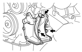
Temporarily install the No. 1 compressor mounting bracket with the 3 bolts.
Tech Tips
Temporarily install the No. 1 compressor mounting bracket with the 3 bolts so that the bracket can be moved by hand.
-
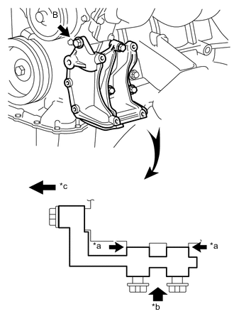
Text in Illustration *a No Clearance *b Push *c Front Push the No. 1 compressor mounting bracket toward the cylinder block as shown in the illustration and tighten bolt B.
- Torque:
- for bolt B
- 45 N*m { 459 kgf*cm, 33 ft.*lbf }
Tech Tips
Make sure there is no clearance between the cylinder block and No. 1 compressor mounting bracket as shown in the illustration.
-
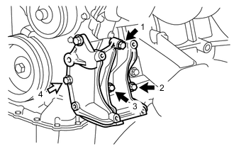
Uniformly tighten the 4 bolts in the order shown in the illustration.
- Torque:
- for bolt A
- 45 N*m { 459 kgf*cm, 33 ft.*lbf }
- for bolt C
- 25 N*m { 250 kgf*cm, 18 ft.*lbf }
Text in Illustration 
Bolt A 
Bolt C
-
-
INSTALL IDLE PULLEY ASSEMBLY
-
Temporarily install the idle pulley assembly with the bolt.
Note
Do not use any tools.
-
Tighten the bolt.
- Torque:
- 44 N*m { 449 kgf*cm, 32 ft.*lbf }
-
-
INSTALL VENTILATION PIPE
-
INSTALL HEATER HOSE
-
Install the 2 heater hoses to the No. 1 water by-pass pipe and No. 2 water by-pass pipe, and slide the 2 clips to secure the hoses.
-
-
INSTALL INTAKE MANIFOLD
-
INSTALL PURGE VSV
-
INSTALL FUEL DELIVERY PIPE WITH FUEL INJECTOR
-
INSTALL THROTTLE WITH MOTOR BODY ASSEMBLY
-
INSTALL EXHAUST MANIFOLD
-
INSTALL AIR SWITCHING VALVE ASSEMBLY
-
INSTALL NO. 4 INTAKE PIPE
-
INSTALL NO. 1 EXHAUST MANIFOLD HEAT INSULATOR
-
INSTALL GENERATOR ASSEMBLY
-
INSTALL IGNITION COIL ASSEMBLY